EE205: Electric Circuits II (092)
Alsalam Alaikum wa Rahmat Allah
Dear EE205-Student,
Welcome to EE205. I pray Allah that you find this course very useful and enjoyable. An excellent start is needed.
This page serves my students in all semesters. It contains model exams, projects,...etc . Some material may be found through WebCT.
Best regards,
Dr. Ali Muqaibel
EE205 -092 Class


Pictures of inductor & capacitors (ppt)
Others
Course Syllabus-092_v1
Homework assignments 092
| HW# |
Practice Assignment Problems |
Solution |
HW Problems to be submitted |
Due Date |
| 1 | HW1 Ch 11 Three Phase Circuits, (Word File) |
All Practice Problems |
Tuesday, Week 3 |
|
| 2 | HW2 Ch 8, Natural and Step Response of RLC Circuits (pdf) |
HW2 (pdf) |
Tuesday Week 5 | |
| 3 | Handout: Chapter 7:State equation and computer aided analysis 6, 9, 21, 25,38, 40 |
HW3 (pdf) |
Sunday, Week 7 | |
| 4 | Handout: Chapter 10: Resonant Circuits: 23, 26, 27, 33 |
HW4 (pdf) |
Tuesday, Week 9 | |
| 5 |
Handout Chapter 10: 40, 42 , 50 , 53, 54 |
HW5 (pdf) |
Sunday, Week 10 | |
| 6 | Chapter 6: 34, 36, 38a, 44,45,46
(8th Edition) Chapter 9: 72, 73,75,77 (8th Edition) (if you do not have the 8th edition click here to get the questions) |
HW6 (pdf) | Sunday, Week 12 | |
| 7 |
Chapter
14: 14.3, 14.6, 14.8,
14.15, 14.20
and 14.25 (7the edition) |
Sol HW7 | HW7 (pdf) | |
| 8 | Chapter 18:
18.3,
18.9, 18.10, 18.11 and 18.12 (7th edition) |
Sol HW8 | HW8 (pdf) |
Exams
|
Material |
Solution 082 |
Solution 092 |
| [11.1-11.3] Balanced Three Phase Circuits | ||
| [11.4-11.6] Power Measurements & Calculations in Three Phase |
|
|
| Chapter 8: Natural and Step Response of RLC Circuits |
Q3 Ver 1& 2 |
|
| Ch11, Ch8, and (Ch7 from the handout) |
M1 Solution |
M1
Solution |
| Computer Aided Circuit Analysis (Handout Ch 7) | ||
| Resonance Frequency | ||
| S-Domain Analysis; Pole-Zero Plot | ||
| Ch 10 (Handout), Ch6+Ch9 (Mutual Inductance and Linear transformers) |
M2 Solution |
M2 Solution |
| Mutual Inductance and transformers | ||
| Filters and Bode Plots |
Q6 Solution |
|
Exams 031
|
Exam# |
Material |
Solution |
| Q1 | [11.1-11.4] | Sec01 , Sec02 |
| Q2 | [11.5-11.6] | Sec01 , Sec02 |
| Q3 | [8.1-8.2] | Sec01 , Sec02 |
| Q4 | [8.3-8.5] | Sec01 , Sec02 |
| M1 | Ch8, Ch11, and (Ch7 from the handout) | Exam, Solution |
| Q5 | Resonant Circuits (Handout 10.3, HW#6) | Short Sol., Long Sol. |
| Q6 | Complex Frequency (S-Domain) | Sec01 , Sec02 |
| Q7 | Mutual Inductance (6.4,6.5, HW#8) | Sec01 , Sec02 |
| M2 | Ch 10 (from handout), Ch 6 & Ch 9 | Exam & Solution |
| Q8 | Filters and Bode plot (HW#10) | Sec01 , Sec02 |
| Q9 | Filters and Bode plot | |
|
F |
Final Exam |
Notes & Summary
|
# |
Material |
Related External Links |
| 1 |
Chapter 11: Balanced Three-Phase Circuits V2.1 (pdf) |
Fundamentals of Electric Circuits by Alexander and Sadiku : Balanced Three Phase Tutorial (CH12) and others (practice) |
| 2 | Chapter 8: Response of RLC Circuits | |
| 3 |
Ch7 Handout (Full) Ch7 Handout (Summary v2.1), (pdf) In Class Group Practice (pdf) |
|
| 4 |
Chapter 10 Handout (Full) Ch10 Handout (Summary: Resonance and Quality Factor) (pdf) |
|
| 5 | Ch 10 (Summary: Complex S-domain Analysis) (pdf) | Explore the S-Domain |
| 6 | Ch6 & Ch9 Mutual Inductance and Transformers (pdf corrected ver. 2.0) |
Transformers (Wikipedia) Transformer Java Example |
| 7 |
Bode Plot Practice Problem 1 Practice Problem 2 SemiLog Paper Generating Program (click here to download) |
(Visit
this Website) Rules for Making Bode Plots |
| 8 | Two port networks (properties: reciprocity and symmetry, ppt) | |
| 9 | Summary of Main ideas in the course (pdf) |
Projects
|
# |
Project Title |
Solution |
Due Date |
| 092 | Matlab Links | Tuesday , May 15, 2010 | |
| 082-1 | Sat., May 30, 2009 | ||
| 031-1 | Mon., Nov. 10, 2003 | ||
| 031-2 | Sat., Jan. 3, 2003 |
Useful Links:
- Online lectures are available at the following link http://ocw.kfupm.edu.sa
Common Mistakes:
These are some common mistakes.... if you find additional common mistakes send them to me to list them. This way we can avoid them and make them less common
1) Analysis of Balanced Three Phase Circuits
-
Mixing angular frequency (rad/sec) with frequency in (Hz). Do not forget to do the proper transformation.
-
Remember that adding or subtracting 360 degrees does not change the angle. (240 is equivalent to -120). Also when using the calculator do no forget to make sure that it is set properly to radians or degrees.
-
When asked to find the three phase voltages or currents, do not forget to find the values for the other two phases.
-
cos is used as a reference with angle zero. If sin is used it has to be converted to sin if need be. sin x= cos (x-90).
-
Line Voltages (VAB,VBC,VCA or Vab,Vbc,Vca) does not equal to voltage drop across the line (VaA, VbB, VcC). This is a very common mistake.
-
If the frequency is negative do not forget to do the proper change on the angle.
-
When using the equation for complex power, the conjugate is usually forgotten.
-
If the total power is given do not forget to divide by 3 to draw the single phase.
-
If the load is given as delta, you need to divide by three to draw the single phase equivalent.
-
If the complex power is give as P+j Q, we cannot directly represent this as resistance and inductance !
2) Natural & Step response of Series and Parallel RLC Circuits
-
alpha for series is different than alpha for parallel circuit. It is very common to mix them.
-
When finding the type of response it is very common to compare mega^2 with alpha.. You should compare omega with alpha.
-
After finding the constant in the response you should assign it to the proper exponent (or expression). It is very common to write A1 in place of A2 and so on.
3)
-
For Q = 2π
Remember that the maximum energy stored is measured after summing W(t)C & W(t)L not individually and do not forget 2π.
- Q is measured at resonance.
- When finding the power lost in R do not forget 1/2 if I is an amplitude value.
- For impedance scaling :
R'=kmR L'=kmL C'=C/km ωr'= ωr BW'= BW
- For frequency scaling :
R'=R L'=L/kf C'=C/kf ωr'=kf ωr BW'= kf BW
- Do not mix up the symbols of poles "X" and zeros "O" in pole-zero plot.
- For the total energy stored in coupled coil
w(t)=1/2 L1 i12(t) + 1/2 L2
i22(t) ![]() M
i1(t) i2(t)
M
i1(t) i2(t)
there is no 1/2 before M.
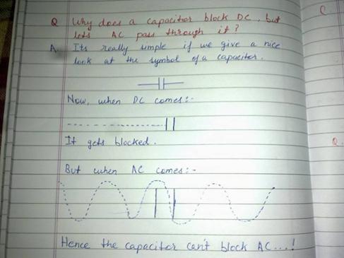
Here is a nice one