|
| |
| |
|
Capstone Projects |
|
Term: 182 (2019)
Name:
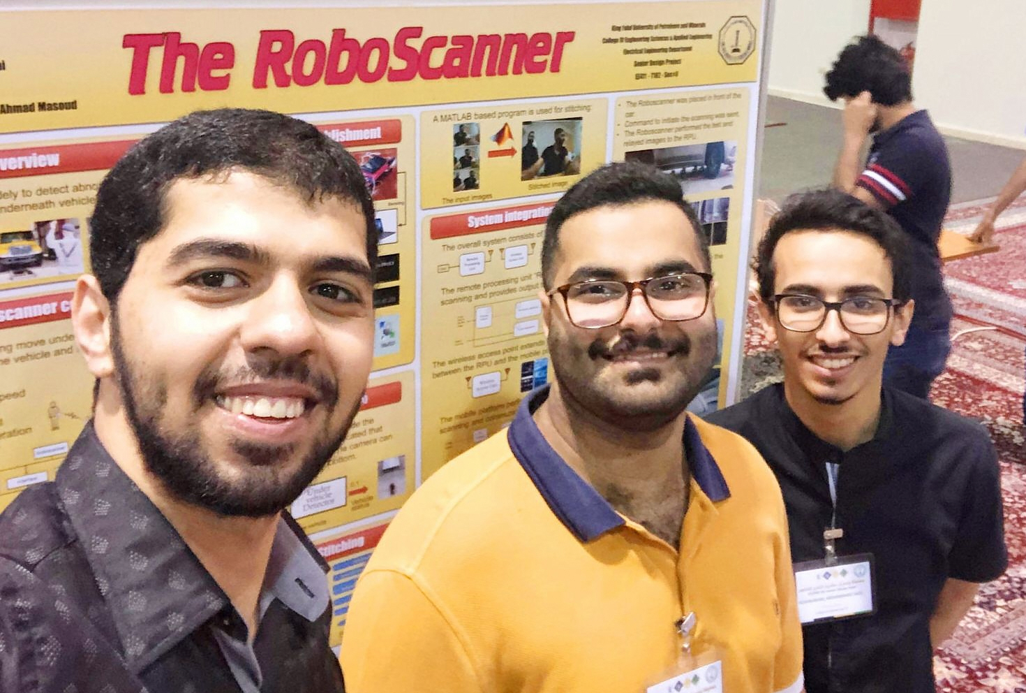
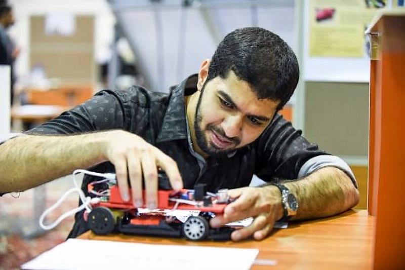
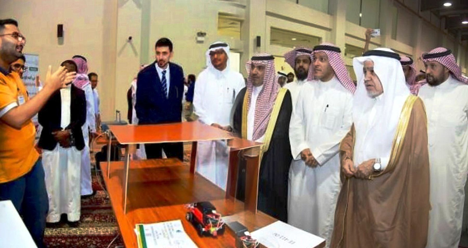
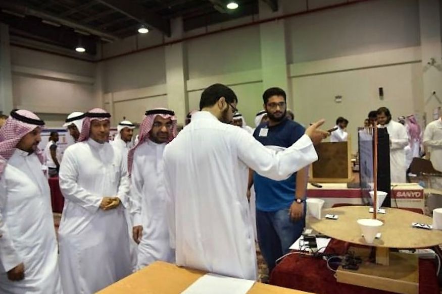
The RoboScanner
YouTube: https://www.youtube.com/watch?v=4tEsC1PqlQY
The project won 4th place in the EE design EXPO:
P1,P2,P3,P4,P5,P6,P7,P8,P9
Description:
The objective of this project is to build mobile scanning element that
can provide an image to a user of the bottoms of objects such as cars.
The system consists of a mobile platform that is carrying a wireless
camera in an upright position. The platform can be ordered to move
forward and in reverse. The camera stream images to a computer or a
smartphone. The stream of images is assembled to obtain a full picture
of the obstructed view of object’s bottom. |
|
|
|
|
|
|
Term: 172 (2018)
Name:
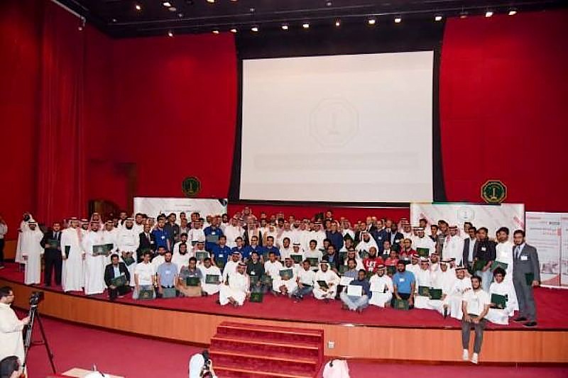
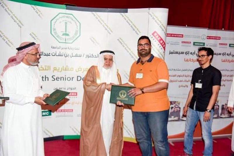
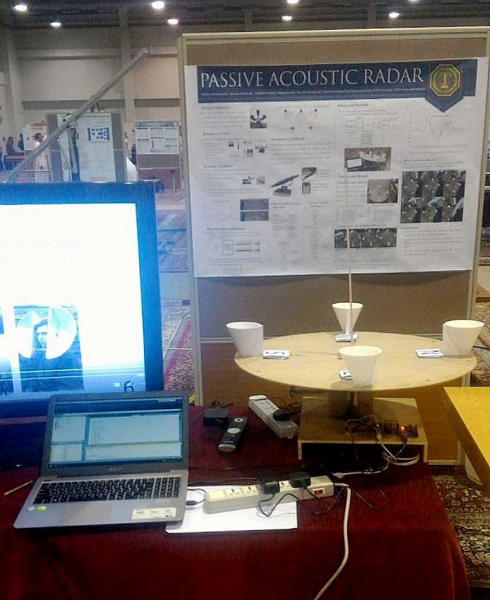
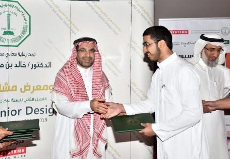
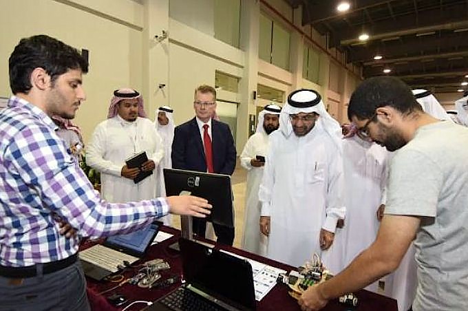
Passive Acoustic Radar
YouTube: https://www.youtube.com/watch?v=mvukr59MXCE
The project won 2nd place in the EE design EXPO:
P1, P2,
P3, P4
Description:
The aim of the project is to construct an integrated mechatronic system
that can function as a passive acoustic radar. The system consists of
acoustic receptors, motorized pan-tilt platform, signal processor and
direction discriminator and a platform actuation controller. The system
aims at tracking an acoustic source and estimating its pose. The system
is designed from basic principles. All components are manufactured
locally. The system is integrated and extensive testing is carried-out
to verify its performance. |
|
|
|
|
|
|
Term: 162 (2017)
Name:
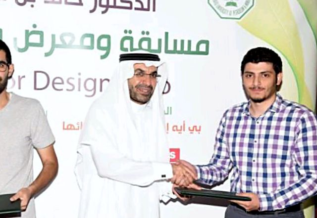
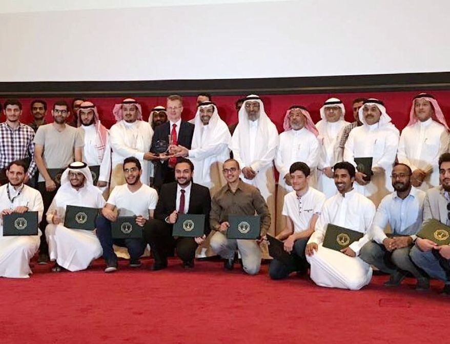
Optical Mouse-Based Odometer and Motion
Tracker
YouTube: https://youtu.be/gwXvvmw8Qg0
The project won 2nd place in the EE design EXPO:
P0,P1, P2,
P3, P4,
P5, P6,
P7,P8
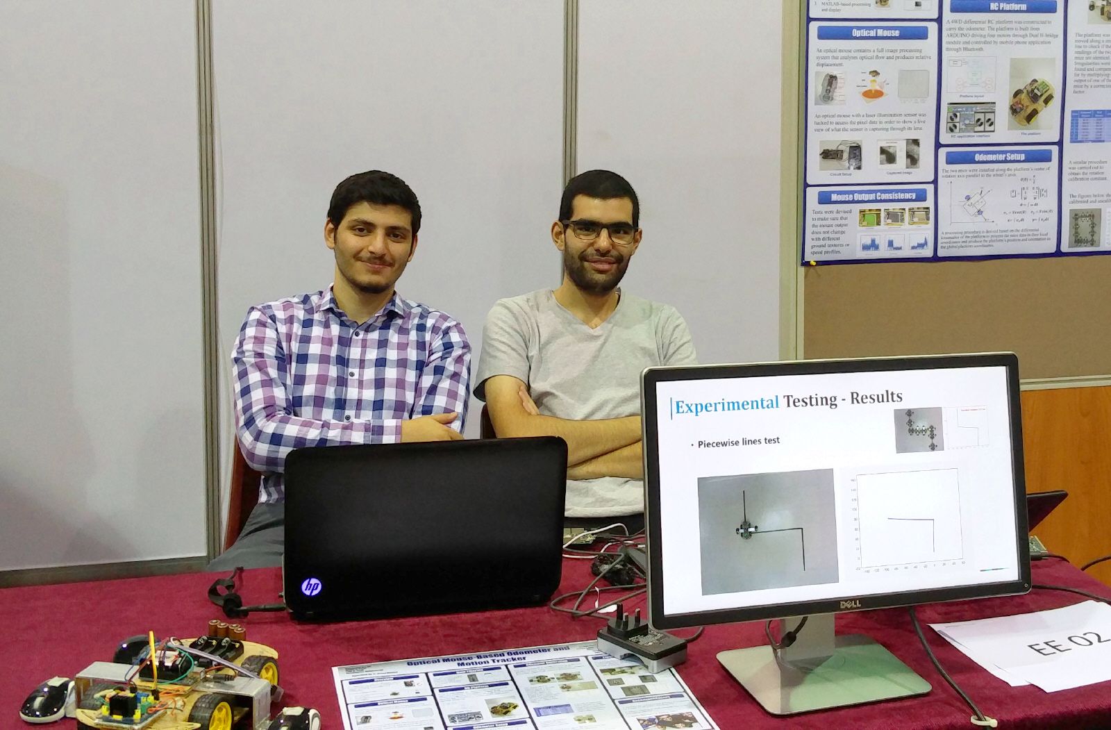
Description:
The
project aims at constructing an inexpensive odometer to record, online,
the trajectory and orientation of a moving platform. The optical
coupling between the platform and its background is carried-out using
two standard computer wireless optical mice. Tests were designed and
carried-out to determine the usability of the mice as measuring device.
The mice outputs are found to suffer from a high amount of noise.
Different filters were tested to suppress this noise. A configuration
for setting-up the mice in order to use them as an odometer is
suggested. A procedure is proposed for processing the mice output in the
adopted setting to produce the position and orientation estimates. An
RC platform was also designed and built to carry the odometer and
experiment with it. Experiments were designed to calibrate the odometer
as a whole system. Thorough experimentation were carried-out to assess
the capabilities of the system. |
|
|
|
Term: 152 (2016)
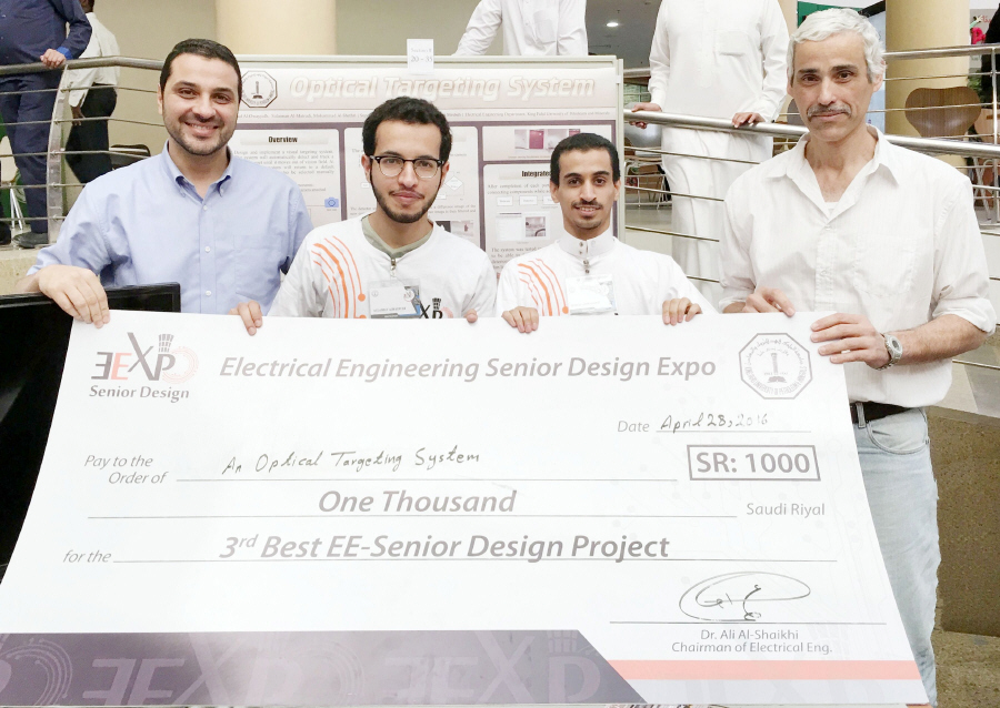
Name: An Optical
Targeting System
YouTube:
https://youtu.be/6wdkDIYCwuY
The project won 3rd Place in the EE design EXPO
Description:
The project tackles the design and implementation of
a basic optical targeting system. The system is required to detect the
entry of an object into the camera visual field, track the object while
maintaining an LED pointer lock on the target. It consists of the
following subsystems: the mechanical pan-tilt platform along with the
needed computer interface, an optical processor and an orienting
controller to interface the processor with the pan-tilt platform. The
design emphasizes the use of affordable hardware. It also restrict
processing to an ordinary laptop and matlab software. Both the hardware
and software environments were developed and interfaced. Thorough
experimental testing was carried-out. |
|
|
|
|
|
Term: 151 (2015)
Name: A
Visually-servoed, Radio Controlled Toy Car
YouTube:
https://youtu.be/yysk84lVGkE
Description:
A
fully
autonomous (push button), visually-servoed system for a car-like robot
operating in free space is built from the ground up. The aim is to
produce an inexpensive system with almost all the functionalities needed
to operate as a test-bed for developing controllers, trackers and other
modules needed for implementing such systems. The car used is an
inexpensive RC toy car that cost about 30 Saudi Riyals (9 USD). The
workspace of the car is visually monitored using a standard 10-USD PC
webcam. The handset of the car was interfaced to matlab via the Aurdino
microcontroller (will be removed in the future). Inexpensive Interface
circuitry (less than 10 USD) was built so that commands to the car can
be sent electronically. Software is developed to online estimate the
state of the car from the sequence of images steamed to matlab. Three
controllers are developed to use the car state and the target point from
the computer mouse to generate an online control hat will move the
car from any where in the visual filed to the specified target point.
|
|
|
| Term: 141 (2014)
Name: An Intelligent Optical
Maze Solver
YouTube:
http://www.youtube.com/watch?v=W6kxll6aqX4
Description:
An intelligent vision system is constructed that is able to
solve any maze a human operator present it with. The maze is fed to the
system using a computer webcam. The start and end points are marked
using a computer mouse. Edge detection is used to segment the image into
obstacles which the path has to avoid and free space which the path can
pass trough. Electromagnetism is used to construct the path by treating
obstacles as an insulator and free space as a perfect conductor. |
| |
|
Term: 132 (2014)
Name:
Maze Solving Using the X80 Mobile
Robot
YouTube:
http://www.youtube.com/watch?v=oSCz1NIUwYs
Description:
A navigation control is designed for a differential drive robot to
move the robot in an unknown environment from one point to another. The
navigator on-line senses the environment using ultrasonic sensors. The
Harmonic potential approach is used to convert the sensor data into an
obstacle-free trajectory for the robot linking the start and end
points. |
| |
| |
| |
| |
| |
| |
| |
| |
| |
| |
| |
|
|
| |
| |
| |
| |
| |
| |
| |
| |
| |
|
Disclaimer: Material are
provided on this page for the sole purpose of timely information
dissemination, and the copyrights belong to the authors and the corresponding publishers
unless otherwise stated. |
| |
|