A storage element maintains binary state indefinitely (as long as
power is applied), until directed by an input signal to switch to its
other state.
The simplest latch, also referred to as the SR latch
has two inputs and two outputs and can be constructed from two NOR gates
as shown.

The behaviour of the above latch in can be illustrated
using the following timing diagram (unlike combinational circuits,
sequential circuits are a function of time) as shown below:

Note that when S and R simultaneously change from their
asserted state to their deasserted states, the flip flop enters an
unstable state when its outputs oscillate between two binary
states indefinitely.
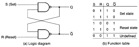
An alternate form of the SR latch, in this case the
set and reset signals active low, can be constructed using
NAND gates as follows:

One way to prevent the system from becoming unstable is by
means of gating the set and reset inputs using a
control input.

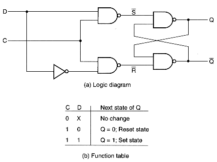
Another way of eliminating the undesirable unstable state
is by means of making sure that both set and reset signals
are never active at the same time giving rise to a what is called a D
latch.