| 5. Cathodic Protection | |
|
5.9 Groundbed Design [3/3] |
|
Calculations for Groundbed Design
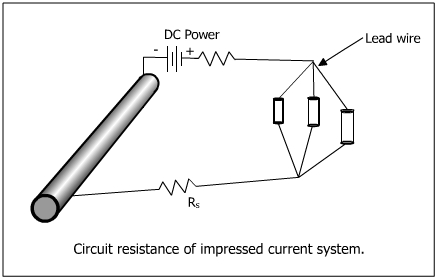
1. Circuit resistance of impressed current system:
Figure below gives the circuit for impressed current systems.
| (a) Circuit resistance | ||
| RC = RS + RLW + Rab | ||
| where | RS = structure to electrolyte resistance | |
| RLW = leadwire resistance | ||
| Rab = anode bed resistance | ||
| (b) Structure to electrolyte resistance | ||
| RS = (VON-VOFF)/ION | ||
| where | VON = structure to electrolyte potential (current ON) | |
| VOFF = structure to electrolyte potential (current OFF) | ||
| ION = current applied to give potential VON | ||
| (c) Maximum allowable circuit resistance | ||
| Rmax = Vmax / Imax | ||
| where | Vmax = maximum driving voltage of power source | |
| Imax = maximum current output of power source (the circuit resistance must not be greater than the maximum allowable circuit resistance, Rmax) | ||
| (d) Anode bed resistance | ||
| The anode bed resistance Rab must not exceed the difference between the maximum allowable circuit resistance and the leadwire resistance. | ||
| Rab = Rmax - RLW | ||
2. Circuit resistance of galvanic anode system:
Figure below gives the circuit for galvanic anode systems.
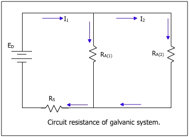
The above diagram shows an equivalent electrical circuit for galvanic anode systems.
| (a) The circuit resistance is given by | ||
| RC = RS + RLW + Rgb | ||
| where | RS = structure to electrolyte resistance | |
| RLW = leadwire resistance | ||
| Rgb = resistance of groundbed | ||
| Rgb = Rlw + Rv | ||
| Rv = resistance of vertical anode to earth | ||
| The anode resistance for multiple anodes is given by (Rlw + Rv)/N, where N is number of anodes. | ||
| (b) Structure to electrolyte resistance | ||
| RS = (VON-VOFF)/ION | ||
| where | VON = structure to electrolyte potential (current ON) | |
| VOFF = structure to electrolyte potential (current OFF) | ||
| ION = current applied to give potential VON | ||
| (c) Maximum allowable circuit resistance | ||
| Rmax = ED / I | ||
| where | ED = driving potential of anode | |
| I = current requirement of structure | ||
| (d) Driving potential of galvanic anode | ||
| EA = solution potential of anode | ||
| EP = protected potential of structure | ||
|
|