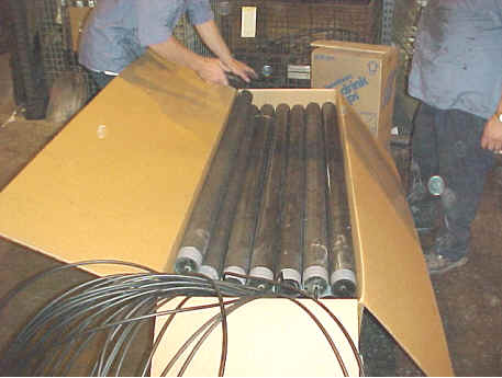
| Graphite Anodes: | They are made by fusing by coke and
carbon particles at a very high temperature. Their operation limit is 0.3
amp/ft2 in fresh water, 1.0 amp/ft2 in salt
water and 1.0 amp/ft2 in soil.
|
||||||
| High Silicon, cast iron | Typical composition is
|
||||||
| Silicon | 14.35% min | ||||||
| Carbon | 0.85% max | ||||||
| Manganese | 0.65 % min | ||||||
| Iron | - remainder - | ||||||
|
The received current density is 1-5 amp/ft^2. It is good for soil and fresh water and sea water.
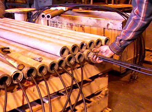
Silicon - Iron tubulars
|
|||||||
| Scrap iron | The consumption rate is 9 kg/amp/year. There
are no restrictions on maximum voltage.
|
||||||
| Platinized Platinum | The rate of consumption is 0.006
g/amp/year. It is very useful for protecting offshore structures.
|
||||||
| Lead silver anodes | Their composition is
|
||||||
| Lead, 1-2 % Bismuth | |||||||
| Lead, 2 % Silver | |||||||
| Lead, 10% Silver, 6% Antimony | |||||||
| They are operated with current densities in the range of 15-50 amp/ft2. The consumption rate is less than 0.2 lb/amp/year. | |||||||

