| 5. Cathodic Protection | |
|
5.3 Cathodic Protection Systems [4/8] |
|
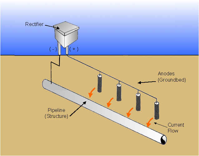
2. Impressed Current Systems
In impressed current protecting system, cathodic protection is obtained by using external anodes of a metal such as scrap iron, silicon cast iron. The current to protect the pipe is provided by a direct current source. A schematic of impressed current cathodic protection system is shown below.
Impressed current anodes of high silicon iron or graphite are buried in coke breeze surrounded by soil. The rods are connected together and form the ground bed. They are located about 300 ft from the pipeline. A direct current supply is obtained from a transformer/rectifier unit designed to step down normal A.C. voltage and rectify it to a direct current. The output from a T/R unit is adjustable over a wide range to suit the current requirement.
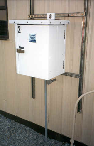
Cathodic Protection Rectifiers
A rectifier is a device which is provided by AC power and converts AC current to DC current. Thus, rectifiers are used as a source of DC power for impressed current cathodic protection systems. The following are the chief components of a rectifier.
Transformer: It steps down the higher AC voltage to a lower AC voltage on the secondary winding. The primary winding is the coil which receives the energy and secondary winding discharges the energy at a changed voltage. The voltage in the secondary winding can be adjusted using connection points called 'taps'. Sufficient taps are provided to allow units to operate from zero to maximum voltage. The output of the secondary winding is connected to a rectifier. A picture of a transformer is shown below.
Rectifying elements: The function of rectifying cell is to pass current in one direction and block it in the opposite direction. The rectifying elements are made of either silicon or selenium. Silicon provides higher efficiency and less aging. Selenium is preferred for high voltage and high current. Selenium diodes are generally used for small rectifiers and silicon diodes for large rectifiers. Silicon element is called a 'diode' because it has a single crystalline junction. An assembly of silicon diodes arranged to rectify AC input and DC output is called a 'stack'. Each stack is made of arms and legs which serve as paths for electrical current. The components for a rectifying element is shown below. The diodes have forward resistance which varies from 1 to 10 ohms and a very high reverse resistance of the order of mega ohms.
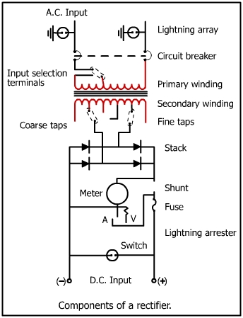
DC meter: Shunt and switches provide a means to monitor the output of a rectifier. Fuses serve as overload protection devices.
Lightning arrestors: These are installed on the input and output. They protect sensitive components like diodes from high current surges caused by lightning.
Circuit breakers: They are placed for protection against overload.
|
|