Examples of Use Case Modeling
Antipatterns
By: Mohamed El-Attar
Ø Antipattern Name
a1. A UC that is used as an
extension and inclusion UC
§ Description
The reuse of a preexisting UC is achieved by making it both an extension UC and an inclusion UC. For example, in a car dealership system (see Figure 1), when a new car arrives at the dealership, it is recorded into the database of the dealership using the Add New Car UC. A precondition to adding the new car to the dealership’s database is that the car must not already exist at the dealership. Therefore, UC Add New Car includes UC Car Not Found to check for that precondition. UC Update Car’s Information is responsible for updating the information related to a particular car, such as, its current mileage or where it is located (assuming several branches). In order to update a particular car’s information, this car must exist in the dealership’s database. An error is generated if the given car does not exist in the database. Therefore, UC Update Car’s Information is extended by UC Car Not Found to handle this error generated.
This eventually leads to the discouraged construct where a UC (Car Not Found), is an extension and inclusion UC.
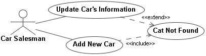
Fig.
1 UC Car Not Found was
incorrectly used for the purposes of containing common functionality and
exception-handling behavior
§ Rationale
Object-oriented modeling and design strongly promotes the concept of reuse. When modelers are constructing their UC models, they are keen to reuse much of the functionality contained preexisting in UCs. UC modeling offers mechanisms through its extend, include and generalization relationship to allow this reuse. Reusing UCs also prevents the cluttering of the UC with many redundant UCs. However, when applying the concept of reuse, the include and the extend relationships can be misused leading to the creation of UCs containing both common and exception-handling behavior.
§
Consequences
The shared UC currently contains common and exceptional behavior required by the two base UCs. Therefore, when either of the base UCs initiate the shared UC, additional undesired functionality is performed. To further elaborate, during the operation of the including base UC Add New Car, UC Car Not Found is initiated to check that the given car does not exist in the database. However, UC Car Not Found will unnecessarily also perform the procedure of trying to update a car’s information that does not exist. On the other hand, if the UC Update Car’s Information is performed to update the information of a given car that does not exist in the database, UC Car Not Found is initiated to handle the generated error. In this situation, the UC Car Not Found will unnecessarily check if the given car does not exist in the system.
§
Detection
Where –Search for any included UCs in the UC diagram. How – If an inclusion UC is found, check if this inclusion UC is extending other UCs.
§ Improvement
Check if the shared UC contains functionality suitable for only one of the base UCs. This can be achieved by examining the contents of the shared UC.
1. If the shared UC contains functionality suitable for only the base UC that includes it, the extend relationship should be removed. A new extension UC should be created to handle the exceptional situation generated by the other base UC. The resulting model is illustrated in Figure 2.
2. If the shared UC contains functionality suitable only for the base UC that it extends, the include relationship should be removed. A new UC should be created and included by the other base UC, again resulting in the model shown in Figure 2.
In both cases (1) and (2), the UCs should be renamed to be more indicative of their respective purposes.
3. In the case that the shared UC does indeed contain both common and exception handling behavior. The shared UC should be split into two separate UCs. Each of the newly created UCs should only contain functionality appropriate to the base UC. Once again, resulting is the same model (see Figure 2).
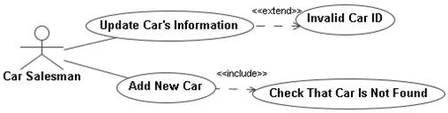
Fig. 2 The
shared UC is broken into two separate UCs, each serving a different purpose
Ø Antipattern Name
a1. Functional decomposition of UCs: Using the include relationship
§ Description
The inclusion UCs represent functions in a program, or menu options instead of a complete service that is offered the system. Such inclusion UCs are not used by any other UC and are not associated with any actors. For example, in the espresso machine system shown below (see Figure 3), the inclusion UCs together are used to prepare a cup of coffee.
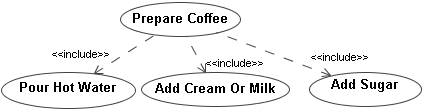
Fig.
3 Functional decomposition
of the Prepare Coffee UC
§ Rationale
Dissecting analytical UCs into functions yields a set of “smaller” UCs that are naturally easier to implement. Overall, this will lead to a speedier implementation of the system. Creating “smaller” UCs is particularly attractive to modelers since they are easier to understand and code. Consequently, in later development phases, the “smaller” UCs will easier to test and maintain. Functional decomposition can be use to embody design decisions that analysts would like to enforce throughout the development of a system.
§ Consequences
UCs should represent services that a system offers to its actors. Being able to abstract the actual service offered by these numerous functions by examining many decomposed UCs is a very difficult task. One can at best guess what service these UCs will offer when performed together. For complex systems, it is more likely that this “guess” will be incorrect. Moreover, functional decomposition of UCs may lead to complex descriptions of the interactions between the actors. Functional decomposition embodies premature design decisions which severely limits the creativity of designers and enforces them to abide to these decisions.
§
Detection
Where – Look for an inclusion
UC inside the UC diagram. How – Upon finding an inclusion UC,
count the number of UCs that include it.
If the inclusion UC is included once, then the antipattern is
matched. It is important to note that in order to match this antipattern; the inclusion
UC must not be associated with any actors or UCs in the UC model.
§ Improvement
The behavior described in inclusion UCs must be combined into UCs that individually offer a complete and meaningful service to a system’s user.
For the espresso machine system shown in Figure 3, the behavior described by UCs Pour Hot Water, Add Cream Or Milk and Add Sugar should be merged into the UC Prepare Coffee. It can be deduced that the user will not benefit from pouring hot water only, or having a cup with only sugar in it. The real value offered to the user is the preparation of a cup of coffee. Hence, from a conceptual point of view, a single UC called Prepare Coffee (which already exists) should be individually responsible for preparing a cup of coffee.
Ø Antipattern Name
a2. Functional decomposition by using an extension UC to extend
multiple UCs
§ Description
Another form of functional decomposition is the improper use of the extend relationship whereby an extension UC extends multiple UCs. If an extension UC contains general behavior that would be useful to more than one UC, this would be a strong indication that the extension UC has degraded into a function since an extension UC inserts additional behavior to a base UC that is very specific to the respective base UC. For example, in the following racquet sports store system (see Figure 4), the UC Equipment Damaged extends both the Sell Racquet and Sell Ball UCs.
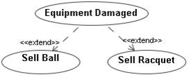
Fig.
4 Improper use of the extend
relationship to promote functional decomposition
It is the employee’s responsibility to ensure that any merchandise being sold is not damaged. Whenever the employee encounters faulty merchandise, the extension UC Equipment Damaged is initiated. In the case of a damaged ball, the defective ball is discarded and a new ball is handed to the customer. Meanwhile, an in-store technician can fix defective racquets, however if the racquet is severely damaged, it is send back to the manufacturer for an exchange. Hence it can be deduced that there are two different procedures for handling defective balls and racquets, yet the structure shown in Figure 9 would indicate a single procedure for handling any type of damaged merchandise.
§ Rationale
Similar
to what is described in the “Rationale” section of the “Functional decomposition
of UCs using the include relationship” antipattern. Moreover, there might be
times where the extension UC is used to provide general functionality
that is specialized by the UCs it extends.
§ Consequences
Similar to what is described in the “Consequences” section of the “Functional decomposition of UCs using the include relationship” antipattern. Moreover, when functional decomposition is applied using the extend relationship; it is often the case that the extending UC does not properly handle the exceptional situations caused by the base UCs. This situation can be easily detected in the racquet sports store system, since the procedure of handling a damaged racquet differs significantly from the procedure of the handling a damaged ball. Therefore, it can be easily deduced that more than one extending UC is required to handle the different exceptional situations occurring.
§
Detection
Where – Search for extension UCs in the UC diagram. How – Upon finding an extension UC, count the number of UCs that the extension UC extends. The antipattern is matched if the extension UC extends more than one UC. It is then required that the analyst examines the behavior described by the extension UC to check if it is too generic. If the extension UC was found to contain specific behavior, it is then required by the analyst to ensure that this specific behavior is in fact suitable for all the extended UCs.
§ Improvement
The behavior described in the extension UCs must be combined into UCs that individually offer a complete service to a system’s user.
For the racquet sports store system illustrated in Figure 4, the extension UC Equipment Damaged should be divided into two separate extension UCs (see Figure 5). Each of the newly created extension UCs will be specifically designed to more appropriately handle the exceptional situations arising at their respective base UCs.
For the case when extended base UCs are used to specialize general behavior described by their respective extension UC¸ a generalization relationship would be more appropriate than an extend relationship to describe such a relationship.
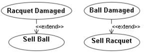
Fig. 5 Extending
UCs disjointed to properly handle different exceptional situations
Ø
Antipattern Name
a3. Using extension/inclusion UCs to implement an abstract
UC
§ Description
An actor is directly associated with an abstract UC that is not implemented through a specializing UC. The implementation of the abstract UC is done through extension or inclusion UCs instead.
§ Rationale
The scenario described above may occur for different reasons:
(1) Modelers find that the inclusion UCs contain subroutine behavior. On the other hand, the extension UCs contain exceptional or optional behavior. Therefore, the inclusion or extension UCs do not contain specialized behavior with regard to the abstract UC and thus should not be modeled using the generalization relationship. Figure 6 illustrates an example of this scenario.
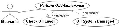
Fig.6 an abstract UC including
subroutine behavior and being extended by a UC containing exceptional or
optional behavior
(2) Extension or inclusion UCs represent specialized behavior with respect to an abstract UC. For example, in Figure 7, the abstract UC Make a Trade can be implemented in the context of making a bonds trade, using the inclusion UC Make a Bonds Trade, or a stocks trade, using the UC Make a Stocks Trade.
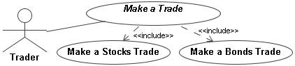
Fig.
7 An abstract UC including
UCs that contain specialized behavior
(3) The model is so far incomplete. At a later point, specializing UCs will be added to implement the abstract UC.
§ Consequences
In first two scenarios described above, the extension/inclusion UCs are used to directly implement the abstract UC. However, extension/inclusion UCs contain behavior different from the behavior specified in the abstract UC. To elaborate, the behavior contained in the extension/inclusion UCs does not realize the behavior described in the abstract UC. Therefore, when the actor initiates a service request, the behavior specified by the abstract UC will never be performed since it is never realized by any UCs. Only specializing UCs may implement abstract UCs.
§
Detection
Where – Search for any abstract UCs. How – (a) the abstract UC is associated with an actor, and (b) the abstract UC is extended by the other UCs or including other UCs, and (c) the abstract UC does not have child UCs.
§ Improvement
(1) In the scenario illustrated in Figure 6, the type of relationships between the abstract UC and the other UCs (Oil System Damaged and Check Oil Level) are appropriate; and hence, should remain unchanged. Unless the model is incomplete, the abstract UC Perform Oil Maintenance should be set as concrete as shown in Figure 8.
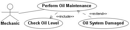
Fig. 8 The abstract UC now set to be concrete
(2) In the scenario illustrated in Figure 7, the usage of the include and extend relationships is incorrect because the extending/included UCs Make a Bonds Trade and Make a Stocks Trade represent specialized behavior with respect to the abstract UC Make a Trade. In this case, the specialization relationship is considered to be the appropriate relationship between the UCs, and therefore this model can be fixed as shown in Figure 9.
(3) The modelers should review and consider adding the missing specializing UC(s) whenever possible.
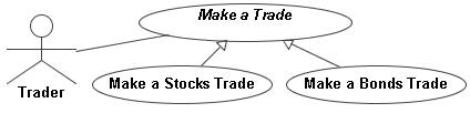
Fig. 9 The abstract UC is associated with its specializing UCs using the generalization relationship
Ø
Antipattern Name
a4. Multiple generalizations of a UC
§ Description
Setting a single UC to specialize two or more UCs.
§ Rationale
Modelers extract common behavior between two or more UCs and create a new specializing UC that will contain this common behavior. For example, preparing either a cargo or a passenger aircraft for a trip requires the cleaning of the aircraft. As shown in Figure 10, the common behavior is contained in the UC Clean Aircraft¸ which specializes the UCs Prepare Passenger Aircraft For Trip and Prepare Cargo Aircraft For Trip.

Fig.
10 Multiple generalizations
of one UC
§ Consequences
The behavioral semantics of the model is violated. The UC Clean Aircraft is not a specialized version of the Prepare Passenger Aircraft For Trip and the Prepare Cargo Aircraft For Trip UCs, which may lead to an incorrect implementation of the system.
§
Detection
Where - Search for a specializing UC. How – If that UC is specializing more than one UC.
§ Improvement
The shared UC Clean Aircraft contains subroutine behavior required by the two other UCs. Therefore, the specialization relationship should be replaced with an include relationship. The include relationship is considered more appropriate since the shared UC contains common behavior not specializing behavior. This solution is illustrated below in Figure 11.

Fig. 11 The generalized UC should be included
by the other UCs that need it
Ø
Antipattern Name
a5. An actor associated with an unimplemented abstract UC.
§ Description
An actor is directly associated with an abstract UC that is not implemented by specializing UC(s) (see Figure 12).
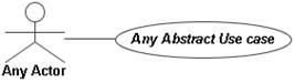
Fig. 12 An actor directly association
with an unimplemented abstract UC
§ Rationale
(1) This situation is most likely to occur when the model is incomplete. The abstract UC will be implemented by specializing UCs in a later phase.
(2) Modelers may incorrectly assume that an abstract UC may be initiated to offer a service to the initiating actor.
§ Consequences
(1) This is an acceptable modeling practice as long as modelers eventually insert the missing specializing UC(s) that will implement the abstract UC.
(2) Abstract UCs cannot be initiated and hence no behavior will be performed.
§
Detection
Where - Search for an abstract UC in the “UC Diagram”. How – If that abstract UC (1) is associated with an actor, and (2) is not specialized by at least one UC. If the abstracted UC is including other UCs or being extended by other UCs then review the “Using extension/inclusion UCs to implement an abstract UC” antipattern.
§ Improvement
(1) Modelers should review and consider adding the missing specializing UC(s) whenever possible.
(2) The abstract UC should be set as concrete. This will enable that UC to be initiated by the actor.
Ø Antipattern Name
a6. Using instances for actors
instead of roles
§
Description
Actors represent instances of a particular role rather than the underlying role itself.
§ Rationale
(1) The modelers incorrectly depict instances of the system’s users instead a class of the system’s users. This situation is illustrated in Figure 13; actors Adam, Jane and Mary are all students who would like to enroll into the university.
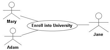
Fig. 13 A model representing instances of an actor
§ Consequences
The model illustrated in Figure 13 violates the true semantics of an actor. This will yield to similar consequences as described above in (1). Moreover, the model will need to be changed frequently as instances of a type of the system’s users are frequently created and removed.
§
Detection
Where –Search for any UCs associated with actors in the UC diagram. How – If the UC is associated with more than one actor.
§ Improvement
(1) In the scenario shown in Figure 13, actors Adam, Jane and
Mary represent the role of a student. Therefore, an actor called Student should be
created that will represent all instances of a student. This solution is
illustrated below in Figure 14.

Fig,
14 The model should
represent the role of a class of users not instances of the
underling roles
Ø
Antipattern Name
a7. Too many UCs.
§ Description
The UC model contains numerous UCs. Detecting this antipattern is dependent on the problem domain. Therefore, identifying how many UCs is too many requires domain expertise and examination of UC models of similar systems. This knowledge will yield an appropriate range for the number of UCs expected. Therefore, this antipattern is matched only if the existing number of UCs far exceeds the appropriate range.
§ Rationale
(1) The system provides new functionalities and services which incorporates new technologies that were not available in older similar systems. Moreover, the system by nature is extremely complex, providing numerous services to many actors.
(2) The UCs are designed to be simple and contain very simple behavior for easier implementation. Such UCs usually contain very short flows, and often represents GUI menu commands.
§ Consequences
(1) This situation is acceptable since systems evolve and become more complex, offering far more services than before.
(2) This is another form of functional decomposition. The UCs offer no meaning individually and contain very little substance. The UCs are only useful when combined and sequenced with other UCs.
§
Detection
Where –The UC diagram. How – If the number of UCs exceeds the expected range.
§ Improvement
(1) No corrective actions are required.
(2) UCs that contain very little substance should be reformed into
uses that offer a complete meaningful service to a system’s user. UCs that
contain implementation details, such as GUI menu commands should be removed and
replaced with analytical UCs that describe what the system needs to do rather
than how it does it.
Ø Antipattern Name
a8. A actor associated with a generalized concrete UC
§ Description
To access this framework of services, an actor is associated with the generalized concrete UC to indirectly access all of the services offered by a set of related UCs.
§ Rationale
An association can be created between an actor and a generalized UC for two reasons:
(1) The generalized UC contains behavior that individually can be useful to that actor.
(2) The operational mechanisms of the generalization relationship in UC diagrams are similar to that of class diagrams. Therefore, modelers may utilize the concept of polymorphism in their UC model. Hence, when an actor initiates a generalized UC, the service request can be delegated to one of its specializing UCs.
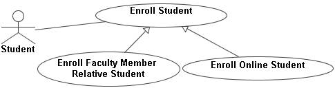
Fig. 15 A good scenario of an actor being directly
associated with a generalized UC
For example, in Figure 15, the UC Enroll Student is a concrete UC that describes the procedure of enrolling a regular student. Special types of students enrolling into the University receive special consideration. A student who is a relative of a faculty member is entitled to a tuition discount, in addition to free access to the University’s health services. This type of student will be enrolled using the Enroll Faculty Member Relative Student UC. On the other hand, the university offers several online programs. Students enrolled in such programs are considered off-campus students and thus they are relieved from paying the University’s health services. Moreover, since online courses are virtual, the system does not need to check for availability inside the classroom. Students enroll into online programs using the Enroll Online Student UC.
In summary, special types of students are enrolled using one of the specializing UCs. Meanwhile, a regular student will be enrolled using the generalized UC.
§
Consequences
Often generalized UCs only contain fragments of general behavior that is used by its specializing UCs. Therefore, generalized UCs are often incomplete. Such incomplete generalized UCs contain “blanks” that are intended to be “filled” by special behavior contained in the specializing UCs. Figure 16 provides a visual overview of the operational mechanisms of the generalization relationship.
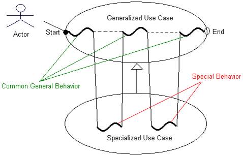
Fig.
16 The execution flow of a generalization relationship
If the generalized UC is concrete, it can standalone as a complete UC which can be exclusively initiated. However, if an actor makes an exclusive initiation request to such generalized UC, incomplete meaningless behavior will be executed. Figure 17 shows a shoe store system that exposes this pitfall.
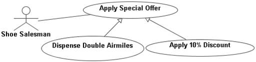
Fig.
17 A bad scenario of an
actor being directly associated with a concrete generalized UC
The shoe salesman may apply one of two promotional offers to a shoe purchase. The first offer allows customers to get double the airmiles they normally would get on their purchases. This offer is applied by performing the Dispense Double Airmiles UC. The other offer entitles customers to a 10% discount on their purchases. This offer is applied by executing the Apply 10% Discount UC. The generalized UC Apply Special Offer is concrete, and it contains general behavior responsible for applying any promotional offer. Since this generalized UC is concrete, it can be exclusively initiated by the Shoe Salesman. If the generalized UC was exclusively initiated, no particular special offer will be applied to a given purchase.
§
Detection
Where – Search for any generalized UCs in the “UC Diagram”. How – – If a generalized UC is found, find out if this generalized UC is concrete. The generalized UC must be associated with an actor. Concrete UCs are labeled using regular font. Meanwhile, abstract UCs are labeled using italic font.
§ Improvement
1. Unlike concrete UCs, an abstract UC cannot be initiated. Setting the generalized UC in the shoe store system shown in Figure 3, which contains incomplete behavior, to be abstract will prevent it from being initiated (see Figure 18):
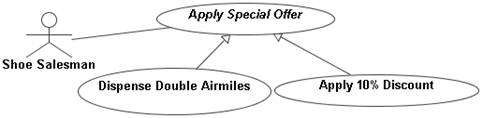
Fig.
18 The generalized UC
is set to be abstract to make sure that one of its specializing UCs
services the actor’s request.
2. Explicit associations between the actor and the specializing UCs can be created in place of the association between the actor and the generalized UC (see Figure 19). The explicit associations with the specializing UCs will enforce the service request to be performed through one of the specializing UCs. Hence, this technique will ensure that the generalized UC is not initiated directly and exclusively. It is worth mentioning that the improved solution presented in (1) is often superior. This approach may cluster the UC model, especially if there are many specialized UCs. Moreover, the solution presented in (1) preserves the semantics behind the original design.
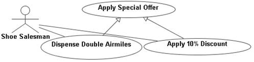
Fig. 19 Direct
access to the generalized UC is avoided and replaced with direct access
to its specializing UCs
Ø Antipattern Name
a9. An actor associated with an extension UC
§ Description
Similar to base UCs, extension UCs can be initiated by actors. Therefore, modelers may associate an extension UC with any actor.
§ Rationale
Extension UCs differ from regular base UCs in that they contain behavior that is of an exceptional or optional nature. Modelers may need an actor to access such behavior contained in an extension UC for a number of different reasons:
(1) If the extension UC contains optional behavior relative to the base UC, this optional behavior may be exclusively useful to an actor. Therefore, an explicit association is created between the actor and the extension UC to allow the actor to execute this optional behavior without needing to initiate the base UC first. This scenario is illustrated using the bookstore system shown below (see Figure 20):
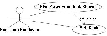
Fig. 20 A good scenario of directly accessing an extending
UC to allow independent initiation of an optional service
The bookstore may occasionally put on a promotion that entitles a customer to a free book sleeve with every purchase of a book. Hence, when the UC Sell Book is performed to complete a sale transaction, the extension UC Give Away Free Bookmark is initiated to carry out the promotional offer. At other times, a bookstore employee may choose to give away a free book sleeve as a courtesy gesture or for advertisement purposes, without a preceding book purchase. Therefore, the Bookstore Employee actor needs to explicitly be associated with the Give Away Free Bookmark UC, to be able to give away free bookmarks without initiating the Sell Book UC.
(2) When an extension UC is handling an exceptional situation, it may be desired to notify a particular actor that such an exceptional situation has occurred. An association is created between the actor and the extension UC to allow the extension UC to notify the actor of the occurrence of such an exceptional situation. For example, in the Internet Service Provider system shown in Figure 21, every time a customer’s account is updated, the system automatically checks if there is any balance due on the customer’s account. If there is a balance due, the extension UC Notify Customer of Balance Due is initiated. The main purpose behind this extension UC is to notify the Customer of the balance due on their account. The extension UC can be configured to send an email or a statement letter to the corresponding Customer.
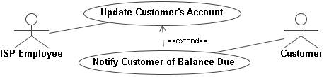
Fig. 21 The extension UC is used to notify
the actor of an exceptional situation
(3) The operation of the extension UC may require certain information to be able to operate. If an actor is the source of this required information, modelers create an association between the actor and the extension UC to allow that actor to convey this required information. The required information was already provided by the actor when the base UC was being performed. This scenario is illustrated in Figure 22.
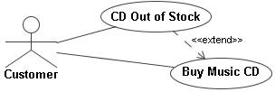
Fig. 22 The actor is allowed to directly access the extension
UC since the actor is the source of information required by the extension
UC
If a Customer attempts to buy a music video that is not available, the extension UC CD Out of Stock is initiated. An association is created between the Customer and the extension UC since it is the Customer that knows the title of the information. The UC records the title of the unavailable CD to notify the store’s manager at a later point. The UC also stores the email address of the Customer to notify that customer when the required CD eventually arrives at the store.
(4) When an extension UC is initiated, it may be desirable to communicate with an actor to retrieve decisions or other information from that actor with regard to the sequence of actions required to handle the exceptional situation at hand. Therefore, an association is created between the actor and the extension UC to form a communication link to allow the decision making process to take place. Unlike situation (3), the required information was not provided by the actor when the base UC was being performed. The bakery shop system presented in Figure 23 illustrates this scenario.
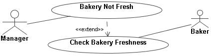
Fig. 23 The extending UC communicates with
the actor decide how to deal with an exceptional situation
If the Baker decides that particular bakery merchandise is not fresh, the extension UC Bakery Not Fresh is initiated. The operation of this extension UC mainly consists of prompting the Manager for a decision with regard to what to do with the expired bakery merchandise. The Manager may opt to:
- Discard the expired merchandise;
- Give it away to shelters and charity;
- Give it away free to customers as a courtesy gesture; or
- Sell it at half price.
§
Consequences
(1) The scenario presented by the bookstore system (see Figure 20) is appropriate because the extension UC contains behavior that is complete and optional. Moreover, it is desirable to execute this optional functionality without initiating the extended base UC.
(2) In the scenario presented by the ISP system shown in Figure 21, the association presented between the actor and the extension UC allows a bi-directional flow of messages between the two entities. This means that the Customer may initiate the extension UC Notify Customer of Balance Due, regardless of an exceptional situation did occurring. Moreover, the Customer may also interfere with the operation of the extension UC when it is initiated.
(3) The scenario presented by the music store system (see Figure 22) is inappropriate because the Customer can directly initiate and interfere with the operation of the extension UC CD Out of Stock. This is an undesired effect because the Customer may convey a different title to the extension UC than was requested by performing the base UC.
In the scenario presented by the bakery shop system shown in Figure 23, the Manager is supposed to communicate with the extension UC Bakery Not Fresh only if the Baker finds bakery merchandise that is not fresh. However, since the navigability of the association between the Manager and the extension UC is not specified, the Manager may initiate the extension UC. This is an undesired effect since the extension UC may be performed even if all the bakery merchandise is currently fresh.
§
Detection
Where – Search for any extension UCs in the UC diagram. How – If the extension UC detected is directly associated with any actor in the model.
§ Improvement
1. Since this situation is deemed acceptable, no corrective actions required.
2. The modelers need to explicitly state that the association between the Customer and the extension UC Notify Customer of Balance Due, is a one-way communication link. Unfortunately, UML lacks the required notation to depict this type of association between actors and UCs. To workaround this limitation, a UML note can be connected to the association link between the two entities to explicitly state that this association is not bi-directional (see Figure 24). Moreover, the navigation direction of the association link can be specified to ensure that interaction between the two entities is started by the extension UC.
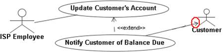
Fig. 24 Setting the navigation allows the UC to
initiate communication with the actor
3. The base UC should be used to convey information to the extension UC. Therefore, the association between the actor and the extension UC should be removed. Instead, the extension UC CD Out of Stock should retrieve the title of the unavailable CD from the base UC that it extends. The base UC Buy Music CD should have the title of the unavailable CD since the Customer would have provided the title when performing the base UC (see Figure 25).
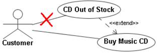
Fig. 25 The base UC should be the one
conveying the extension UC its required information instead of the actor
4. The bakery shop system requires the Manager to communicate with the extension UC Bakery Not Fresh, in order to convey the Manager’s decisions. The current association between the two entities satisfies this need. However, it is also required that extension UC initiates the interaction between the two entities. This can be achieved by setting the navigation direction of the association link as shown in Figure 26.

Fig. 26 Setting
the navigation direction to ensure that the actor does not start the
interaction with the extension UC
Ø Antipattern Name
a10.
Functional decomposition by
creating a call sequence between UCs using pre and postconditions
§ Description
The pre and postconditions in UCs are used to explicitly declare a virtual call sequence between the UCs. If a base UC is decomposed into “smaller” base UCs, it is often the case that the “smaller” UCs need to be performed in particular sequence to properly execute the intended complete service. UC modeling deliberately does not provide an invoke mechanism between UCs since UCs are expected to provide complete services without the need to communicate with each other. It can be deduced that the virtual sequence would most likely be the result of UCs degrading into functions. For example, in a telecommunications system, a base UC that is intended to make a phone call is instead decomposed into the “smaller” UCs shown in Figure 27. The “smaller” UCs: Get Dial Tone, Retrieve Phone Number Dialed, Establish Connection and Ring Destination Phone need to execute in the sequence to properly make a phone call.
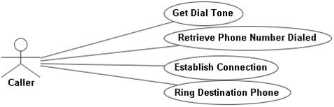
Fig.
27 Sequencing a set of UCs
to make a phone call
There are two methods that can be used to apply this concept (see Figure 25):
· Assuming two UCs named “N” and “N+1” respectively. A virtual call sequence can be enforced between these two UCs by stating as a postcondition for UC “N” that UC “N+1” must start and stating as precondition to UC “N+1” that UC “N” must successfully be completed (see Figure 28). Recalling the telecommunications system from Figure 27, initiation of Retrieve Phone Number Dialed UC is stated as a postcondition of UC Get Dial Tone. Similarly, the successful termination of UC Get Dial Tone is stated as precondition of UC Retrieve Phone Number Dialed.
· Implicitly, by restating the postconditions of UC “N” as the preconditions UC “N+1”. Even though this method may be valid at times, it most likely will lead to the over-specification of the conditions in one of the UCs.
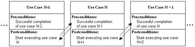
Fig.
28 Creating a virtual call
sequence between UCs using pre and postconditions
§ Rationale
Similar to what is described in the “Rationale” section of the “Functional decomposition of UCs using the include relationship” antipattern.
§ Consequences
Similar to what is described in the “Consequences” section of the “Functional decomposition of UCs using the include relationship” antipattern.
§
Detection
Where – In the preconditions and postconditions of each base
UC. How – (a) If it is stated as a postcondition for a UC that
another UC needs to be initiated, then the antipattern is matched. (b) If it is
stated as a precondition of a UC requires that another UC needs to be
successfully completed, then the antipattern is matched. (c) The antipattern is
matched if is found that the precondition of a UC and a postcondition of
another UC, state similar requirements for a particular variable value.
Naturally, it is more difficult to detect this situation as it requires further
examination of the descriptions of the respective UCs.
§ Improvement
UCs that represent portions of a complete behavior must be reformed into UCs that individually offer a complete meaningful service to a system’s user. Therefore, for the telecommunications system illustrated above, since carrying out a phone call is the real purpose behind the existence of the “smaller” base UCs, the functionality of the sequences UCs should be combined into a single UC called Make A Phone Call.
Ø
Antipattern Name
a11.
Representing devices as
actors.
§ Description
Devices such as printers, keyboards, scanners…etc, are represented in the UC diagram as actors. This antipattern is a specialized version of the “An actor inside the system boundary” antipattern and should be searched for after searching for the “An actor inside the system boundary” antipattern.
§ Rationale
(1) An input/output device is believed to be actor since it is the actual means of I/O into and out of the system. As shown in the Figure 29, the Enter billing information UC is associated with the actor Keyboard.
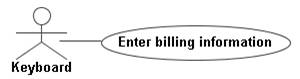
Fig.
29 A Keyboard actor is used
to enter billing information
(2) Often the fundamental goal of a UC is to utilize a given input/output device. For example, a UC that is responsible for printing statements to customers is associated with a Printer actor. This association stems from the fact that main goal of the UC is to produce hardcopies of statements (see Figure 30). Therefore, a printer device will always be required to perform this UC.

Fig.
30 A Printer actor is
required to print statements
§
Consequences
(1) Input and output devices are not systems or actors. They only facilitate the input and out of data. Input devices are not the source of information; and output devices are not the actual beneficiary of the information produced. Therefore, the true source of information provided to the system, and the true beneficiary of the information produced by the system, is unclear.
(2) Even though a particular device is required to perform the objective of a UC as depicted in Figure 30, the UC model should not detail these devices. The system should only be responsible for producing and accepting required information, regardless of the mechanism used to achieve these purposes. This decreases the flexibility and modularity of the system and adds unnecessary constraints in the design, as the system is internally designed to deal with particular devices. For example, if the system was required to send statements to customers via email instead of mailing hardcopies to them, then significant changes are required to accommodate the new requirement.
§
Detection
Where – For every actor present in the UC diagram. How – If the actor’s name resembles an input or output device.
§ Improvement
(1) The actual source of information should be the actor instead of the input device. Similarly, for generated information, the beneficiary of the information should be the actor instead of the output device. Therefore, in Figure 29, the billing information required by the Enter billing information UC was provided by the Customer. A keyboard was only used to facilitate the input of the billing information (see Figure 31).
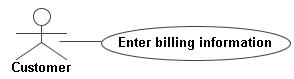
Fig.
31 The Keyboard actor is
replaced with the actual actor Customer
(2) Input/output devices should not be considered in the UC model. This requires that input/output devices should not be depicted as actors in the UC diagram. Input/output devices should only be considered in the description of the UCs
Ø
Antipattern Name
a12.
Very large alternative flows.
§ Description
The description of a UC contains a very large alternative flow. The alternative flow spans several pages and describes very complex behavior.
§ Rationale
Firstly, modelers may not realize that extension UCs can be used to describe very large and complex alternative flows. Secondly, modelers may want group all the information related to the operation of one UC inside that UC. As an alternative, modelers resort to writing large alternative flows.
§ Consequences
Alternative flows are used to describe small deviations from the basic nominal flow of a UC. A very complex or large alternative flow may obscure the real purpose of the UC. Such alternative flows significantly reduce the readability of the UC.
§
Detection
Where – For every UC described. How – If the UC is not depicted in the UC diagram.
§ Improvement
Extension UCs can be used to describe large and complex alternative flows. This in turn allows the original (which then would be a base) UC to be more readable and its main purpose to be clearer.
Ø
Antipattern Name
a13.
Duplicating functionalities
for the generalized and specializing UCs
§ Description
The relationships that a generalized UC has with other UCs are duplicated for the specializing UC. As shown in Figure 32, the UC Authenticate User is included by both the Perform Transaction and Withdraw Cash UCs. Moreover, the UC Insufficient Funds is an extension UC for both the Perform Transaction and Withdraw Cash UCs.
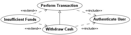
Fig.
32 Duplicating
functionalities for the generalized and specialized UCs
§ Rationale
Modelers try to establish that the behavior contained in the inclusion and extension UCs are applicable to both the generalized and the specializing UCs.
§ Consequences
This situation will probably lead to the creation of duplicated or redundant code at the implementation phase. This redundant code will be the implementation of the inclusion and the extension UCs.
§
Detection
Where - Search for a generalization relationship between two UCs in the UC diagram. How – If both the generalized and specializing UCs have similar relationships with other UCs in the model.
§ Improvement
The modelers need to determine whether a given included or extending UC is applicable to all of the specializing UCs or only a subset of them. For example, the Authenticate User UC must be executed to allow for any transaction to be performed. Therefore, the Authenticate User UC is applicable to all of the specializing UCs and thus there should be one include relationship in the model between the Authenticate User and the Perform Transaction UCs as shown in Figure 32. On the other hand, the extension UC Insufficient Funds describes exceptional behavior responsible of handling a situation where a user requested to withdraw a cash amount that is larger than what is available in the user’s account. Hence, UC Insufficient Funds is only applicable to the Withdraw Cash UC, and therefore there should only be one extend relationship between the Withdraw Cash UC and the Insufficient Funds UC as shown in Figure 33.
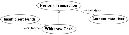
Fig. 33 Only the
appropriate include/extend relationships remain
Ø
Antipattern Name
a14.
UC initiated by two actors
§ Description
Two actors are associated with one UC. The associations point towards the UC meaning that the UC was initiated twice. As shown in Figure 34, UC Withdraw Funds is initiated by the actors Customer and Bank System.
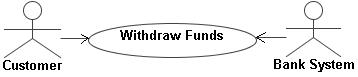
Fig. 34 Two actors initiating one UC
§ Rationale
(1) This situation usually occurs because association links are mistaken for information flow links. When the two actors are providing the UC with information, then the associations with the UC are directed towards that UC. In the ATM system shown in Figure 34, the Customer actor provides the PIN for the UC, meanwhile the Bank System actor provides the UC with this Customer’s current balance.
(2) Both actors play a similar role when the UC is being performed.
§ Consequences
(1) It is not possible to determine which actor initiates the UC. Usually the primary actor is the one that initiates a UC since the primary actor is the primary beneficiary of the service provided by the UC. Therefore, it will be not be intuitive to determine the primary actor.
(2) Unless extreme care was taken during the authoring of the UC description. Designers will not be able to determine the correct sequence of interactions between the actors and the UC.
(3) See the “A UC is associated with more than one actor” antipattern.
§
Detection
Where - Search for a directed association relationship in the UC diagram that is pointing towards a UC. How – If the UC has another association relationship pointing towards it.
§ Improvement
(1) The sequence of interactions between the actors and the UC should be reconsidered. Upon determining which actor is the one responsible for initiating the UC, all other association relationship links connected with the UC should be set to be bi-directional or directed towards the non-initiating actors instead. For the ATM system, it is the Customer that initiates the Withdraw Funds UC and the interaction with the Bank System is always initiated by the UC to determine the Customer’s current balance. Therefore, the association relationship with the Bank System should be directed towards the Bank System, as shown in Figure 35 below.
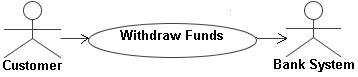
Fig. 35 Only one actor should initiate a UC
(2) See the “A UC is associated with more than one actor” antipattern.
Ø
Antipattern Name
a15.
Two actors with the same name
§ Description
Two actors existing within a UC diagram with identical names. For example, the system shown in Figure 36 has two sets of UCs. Each set of UCs carries out a certain category of administrative duties. The UC sets are associated with two actors named Administrator.
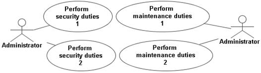
Fig. 36 Two different actors with the same name
§ Rationale
(1) This situation may occur if the actors’ roles are carried out by different personnel with similar job titles.
(2) To enhance the layout of the UC diagram. Using several instances of the same actors may prevent the cluttering of the diagram.
(3) Each instance of the actor is associated with a set of UCs that represents a certain category of services.
§
Consequences
For all three cases presented above, using two actors with similar names may cause confusion as to whether the actors are actually similar or is there any subtle differences between them. Designers may account for two distinct actors in their design while the actors where actually the same entities and vice versa, leading to redundant or incorrect implementation respectively.
§
Detection
Where – For every actor in the UC diagram. How – If another actor exists with the same name.
§ Improvement
(1) The actors should be given names that further distinguishes between them and represents their duties more accurately (see Figure 37).
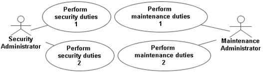
Fig. 37 The actors are given more distinguishing
names
(2) The consequences of depicting the same actor twice overweigh the layout benefits that can be achieved by doing so. The layout of the UC diagram can be improved by reconsidering the positioning of each diagrammatic entity without the need to depict the same actor twice. However, if the diagram’s layout and readability will radically improve, then this modeling practice can be warranted. In this situation, the actors should be annotated with UML notes to explicitly state that they are the same.
(3) Each set of UCs associated with one instance of the given actor represents a separate subsystem. Subsystems can be considered as separate UC diagrams which warrants the depiction of an actor present in a different UC diagram (see Figure 38).
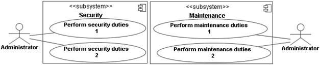
Fig. 38 Two subsystems are presented as two UC
diagrams, both containing the name actor
Ø
Antipattern Name
a16.
An actor inside the system
boundary
§ Description
An actor is depicted within the system boundary.
§ Rationale
(1) The actor represents the system itself and is depicted inside the system boundary for labeling purposes.
(2) The actor represents an internal device which the system depends upon such as a timer.
(3) The actor plays the role of the secondary actor for all UCs, whereby that actor only aids in providing a service to the primary actors but is never the beneficiary actor.
§ Consequences
(1) This situation may cause confusion since the system itself is depicted as an actor. Actors are external entities to a system, therefore depicting the system as an actor may lead the model reader to believe that the system itself is an external entity. Therefore, it would seem that the actual system represented by the UC model does have a name.
(2) Timers and other input and output devices are not systems. Such devices only facilitate the input and output of information. However, if it is necessary to represent a device as an actor, the actor should remain outside the system boundary. Leaving the actor inside the system boundary may lead designers to believe that the device is a part of the system which needs to be designed and implemented. The unnecessary additional effort spent designing such entities (actors) causes the system to be more complex and often causes the project to be behind schedule and over budget.
(3) Even if the given actor is always a secondary actor, the actor should remain outside the system boundary. The consequences of leaving the actor inside the system boundary are similar to that described previously in (2).
§
Detection
Where – Within the system boundary in the UC diagram. How – If an actor can be detected inside the system boundary.
§ Improvement
(1) The system boundary should be labeled with the system’s name only and without using an actor icon. The actor icon used to represent the system itself should be removed.
(2) If the device is merely an input/output device, then the device should not be represented as an actor. If it is necessary represent the device as an actor, the actor should be located outside the system boundary.
(3) Secondary actors as any other type of actors should be located outside the system boundary.
Ø
Antipattern Name
a17.
An unassociated UC
§ Description
A UC is depicted in the UC diagram that is not associated with any other entity. This means that the UC does not have an association relationship with the any actor and does not have any include, extend or generalization relationship with any other UC.
§ Rationale
(1) The UC represents an internal functionality that the system needs to perform.
(2) The association relationship notation between the UC and an actor in the UC diagram, or another entity such as a package or a subsystem, is missing.
(3) The include, extend or generalization relationship notation between the UC and other UCs is missing.
§ Consequences
(1) The purpose of UC modeling is to show the interactions that occur between a system and its external entities in order to provide a service to an actor. Internal functionalities do not offer an immediate service to actors.
(2) This situation may lead to a faulty design since the involved actors are not accounted for during the design.
(3) This situation may lead to unnecessary additional design effort since the behavior of the UC is dependent on the behavior of other UCs which have already been accounted for in the design process.
§
Detection
Where – For every UC in the UC diagram. How – If the UC does not have an association relationship with the any actor and does not have any include, extend or generalization relationship with any other UC.
§ Improvement
(1) UCs representing internal functionalities that do not provide any service to any actor should be removed.
(2) Association relationships should be depicted between the UCs and any actors involved with it.
(3) The correct type of relationship should be depicted between the UCs and any other UCs that are involved with it.
Ø
Antipattern Name
a18.
Very large alternative flows
§ Description
The description of a UC contains a very large alternative flow. The alternative flow spans several pages and describes very complex behavior.
§ Rationale
Firstly, modelers may not realize that extension UCs can be used to describe very large and complex alternative flows. Secondly, modelers may want group all the information related to the operation of one UC inside that UC. As an alternative, modelers resort to writing large alternative flows.
§ Consequences
Alternative flows are used to describe small deviations from the basic nominal flow of a UC. A very complex or large alternative flow may obscure the real purpose of the UC. Such alternative flows significantly reduce the readability of the UC.
§
Detection
Where – For every UC described. How – If the UC is not depicted in the UC diagram.
§ Improvement
Extension UCs can be used to describe large and complex alternative flows. This in turn allows the original (which then would be a base) UC to be more readable and its main purpose to be clearer.
Ø
Antipattern Name
a19.
Using the term “actor” in
textual descriptions
§ Description
The description of a UC makes a reference to one of its involved actors by using the term “actor”.
§ Rationale
(1) The UC is associated with one actor. Therefore, the “actor” in this case is known since there is only one.
(2) Several actors involved with a UC play the same role. Therefore, it is redundant to state each actor by name. It is easier to use the term “actor” to refer to any of the involved actors.
§ Consequences
(1) Using the term “actor” reduces the clarity of the UC description as supposed to using the name of the actor. A larger issue can also occur as the UC model evolves, if at a later stage another actor was associated with the UC, then the term “actor” will become ambiguous.
(2) This situation is a result of another antipattern match. The consequences of this situation are described in the “A UC is associated with more than one actor” antipattern. More specifically, this situation is similar to the first situation (1) stated in the “A UC is associated with more than one actor” antipattern.
§ Detection
Where – In the description of every UC. How – If the term “the actor” was used anywhere throughout the description of a UC.
§ Improvement
(1) The term “actor” should be replaced with the actor’s real name.
(2) This situation can be corrected by addressing the originating “A UC is associated with more than one actor” antipattern match. The appropriate actor names should then be used in the UC description.
Ø
Antipattern Name
a20.
An association between two
actors
§ Description
Two actors in the UC diagram are associated with an association relationship.
§ Rationale
(1) The actors need to communicate and exchange information in order to perform one or more UCs.
(2) One actor is a specialization of the other.
§ Consequences
(1) A system needs only to account for the interactions between itself and its actors. The design and implementation of the system will be based solely on these interactions. Accounting for communications between actors or other external systems will add unnecessary complexity to the design. Moreover, assumptions made with regard to the interactions occurring between external entities can be incorrect or inaccurate.
(2) A generalization relationship between two actors shows the hierarchical relativity between the roles played by these actors. On the other hand, an association between two actors shows that the actors are communicating. Misrepresenting a generalization relationship as an association relationship will lead to similar consequences to those described in (1).
§ Detection
Where –
For every actor in the UC diagram. How – If an actor is associated with
another actor by an association relationship.
§ Improvement
(1) The association relationship should be removed. This allows designers to focus only on the interactions between the actors and the system. Designers should not worry about interactions that occur outside the system.
(2) The association relationship should be removed and replaced with a generalization relationship to reflect the actual relationship between the actors.
Ø
Antipattern Name
a21.
An association between UCs
§ Description
Modelers require two UCs to communicate in order to carry out a meaningful and complete service. The two UCs involved are then linked to each other using an association relationship.
§ Rationale
The scenario described above may occur due to different reasons:
(1) Each UC needs to provide information in order to carry out the
required service for the user. This scenario is shown in Figure 39. The UC Count Shaft Rotations in Trip
is responsible to calculate the distance traveled during a given trip.
Meanwhile, the UC Measure Time of
Trip keeps track of the time elapsed during that trip. The UCs Count Shaft Rotations in Trip
and Measure Time of Trip
each provide necessary information in order to calculate the average speed
of the trip.
![]()
Fig. 39 Two UCs trading information to provide a
service
(2) One of the UCs need to initiate the other UC in order to carry
out a subroutine. This scenario is shown in Figure 40. The UC Calculate Average Trip Speed
initiates the UCs Count
Shaft Rotations in Trip and
Measure Time of Trip in order to retrieve information necessary to
calculate the average speed of the current trip.
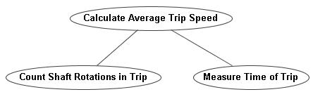
Fig. 40 A main UC is communicating with other UCs by
“calling” them to retrieve necessary information
(3) One of the UCs contains exceptional or optional behavior
relative to the other UC. This scenario is shown in Figure 41. The UC Trip Has Not Started is
responsible for handling the error resulting from attempting to calculate the
average trip speed (when UC Calculate
Average Trip Speed is being
performed) before a trip has even started. The error is caused since the
distance and time elapsed are both 0.
![]()
Fig. 41 A UC communicating with the other to provide
exceptional behavior
§
Consequences
(1) In the scenario presented in Figure 39, the UC model is used as a design tool instead of an analysis tool. The modelers used the UC model to show internal implementation decisions. This obscures the real functionality and services offered by the system to its users, leading to confusion between various stakeholders. Moreover, descriptions of the UCs will include instructions about the two UCs communicating with each other. Therefore, at the implementation phase, every time the average trip speed is calculated, the elapsed will be unnecessarily measured as well, and vice versa.
(2) In the scenario presented in Figure 40, the true semantics of the relationship between the UCs are violated. The initiated UCs Count Shaft Rotations in Trip and Measure Time of Trip contain subroutine behavior and thus do not need to know about the internal behavior of their initiating UC. However, an association relationship between two UCs requires the UCs to be aware of each other’s behavior. Therefore, the initiated UCs will require additional descriptions that will allow them be aware of the initiating UC.
(3) In the scenario presented in Figure 41, the true semantics of the relationship between the UCs are violated, since the Trip Has Not Started UC contains error-handling behavior with respect to the Calculate Average Trip Speed UC. The Calculate Average Trip Speed UC provides complete behavior individually. Hence, it is not required to be aware of the Trip Has Not Started UC. As mentioned before in (2), an association relationship between two UCs requires both UCs to be aware of each other’s behavior. Therefore, the Calculate Average Trip Speed UC will require unnecessary additional descriptions that will allow it to communicate with the Trip Has Not Started UC.
§
Detection
Where – The Analyst needs to search for any pair of UCs in the UC diagram. How – If the UCs are connected with each other using an association relationship.
§ Improvement
(1) This situation is yet another form of functional decomposition. The UCs shown in Figure 39 need to be merged into one UC that will individually calculate the average trip speed. The newly formed UC maybe called Calculate Average Trip Speed. Therefore this scenario can be fixed as shown in Figure 45.
![]()
Fig. 42 Communicating UCs merged into one
However, in the case that the UCs need to remain separated, a new UC that will be responsible of calculating the average trip speed should be created. The newly created UC may then be set to use the existing UCs using the include relationship as shown in Figure 43 to calculate the average trip speed.
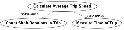
Fig. 43 Communicating UCs are included by a
UC that provides a separate complete service
(2) The initiated UCs in Figure 40 Count Shaft Rotations in Trip and Measure Time of Trip contain subroutine behavior required to calculate the average trip speed. These subroutine behaviors should be able to execute regardless of the context they are initiated in. Therefore, the association relationship between the UCs should be replaced with the proper include relationship as shown in Figure 43.
(3) The initiating UC in Figure 41 Trip Has Not Started contains exceptional behavior with regard to the Calculate Average Trip Speed UC. Moreover, the UC Calculate Average Trip Speed provides complete behavior in the case of no exceptional events occurring. Therefore, the association relationship between the UCs should be replaced with the proper extend relationship as shown in Figure 44.

Fig. 44 The UC containing exceptional behavior now extends
the base UC