
Figure 6-1. We Are Here -- The Definition Phase
| Design |
6.1. What
Is Software Design?
6.2.
Fundamental
Design
Principles
6.2.1.
Modularity
6.2.2.
Abstraction
6.2.2.1.
Functional
Abstraction
6.2.2.2.
Data
Abstraction
6.2.2.3.
Control
Abstraction
6.2.2.4.
Levels
of
Abstraction
6.2.3.
Information
Hiding
6.2.4.
Understandability
and
Uniformity
6.2.5.
Reusability
6.2.6.
Adaptability
6.2.7.
Aesthetics
6.3.
Coupling
and Cohesion
6.4. Formal
Design
Techniques
6.4.1.
Stepwise
Refinement
6.4.2.
Levels
of
Abstraction
6.4.3.
Structured
Design
6.4.4.
Jackson
Structured
Programming
6.5. Object-Oriented
Design
6.5.1.
Object-Oriented
Design
Examples
6.5.1.1.
Graphics
Editor
6.5.1.2.
Compiler
6.5.1.3.
Hardware
Control
6.5.2.
Inheritance
6.5.3.
Choosing
Objects
6.5.4.
Advantages
of Object-Oriented
Design
6.6. User
Interface
Design
6.6.1.
User
Types
6.6.2.
Interaction
Methods
6.6.3.
Design
Guidelines
6.7. System
Architecture
Description
6.7.1.
System
Architecture
Checklist
6.7.2.
An
Example System
Architecture
6.8. Project
Overview
Presentation
6.8.1.
Content
6.8.2.
Organizational
Issues
6.8.3.
Slide
Construction
6.8.4.
Tips
on
Delivery
6.8.5.
Overview
Presentation
Checklist
6.8.6.
Example
Overview
Presentation
6.9. Humor
-- Real Programmers Don't Eat
Quiche
6.10. References
We are now about to enter the second phase of our software development
project -- the Definition Phase. During the first phase, the Concept Phase, we
took ideas with respect to what the software is supposed to do, and
produced a written description of the software requirements -- the initial
requirements (and later, a requirements specification). During the Definition
Phase, we will use these requirements as input and, through the process of
design, produce a design specification -- a written description of the design,
as shown in Figure 6-1.
This chapter discusses design issues, paying particular attention to fundamental
design principles. The concepts of coupling and cohesion are described, along
with an overview of design techniques and object-oriented design in particular.
Issues in the design of user interfaces are discussed, and the chapter concludes
with an example of a high-level system architecture and an overview presentation
for the GEEK project.
Using our construction analogy once again, the architect, working with the customer, produced a set of requirements for a house (number of bedrooms, style, cost, location) in the Concept Phase. During the Definition Phase the architect would produce a design for the house that meets the customer's requirements. In architecture, this design takes the form of a blueprint, which can be used to actually construct the house. In fact, that is exactly what the design specification for your software will be -- a blueprint for the construction, or implementation, of your software.
What are the activities that must be performed during the design process? Fairley [Fairley 85] identifies the design activities as
These are the issues with which we will be concerned during software design.
Software design is, at least currently, a fundamentally creative process. Over the years, many software design techniques have been developed in an attempt to reduce software design to at least a semi-automatic process. Many design techniques have come and gone 1, but certain fundamental design concepts remain constant. Good designs generally exhibit these concepts. These fundamental design concepts are
These fundamental design concepts impact not only the initial design of a software system, but their effect can be felt during implementation, testing, and documentation of the software, and even much later when the software goes into the maintenance phase of its life cycle. A poor design can be very difficult to implement, test, and document, and even more difficult to maintain. A good design which follows these principles provides for a good hierarchical decomposition of the problem, ease of rapid prototyping, improved software reliability, increased reusability, and ease of modification and maintenance. Thus, it is very important to make use of these fundamental design principles early on in the design.
We will now look at these fundamental design principles one by one. However, they are not each a completely independent concept, for they are often inter-related. The use of one design principle usually leads to the use of others.
Modularity is the single most important fundamental design principle. Modularization is the decomposition of the software into components, or modules. A module is a somewhat vague concept, that can best be described, not by a definition, but by giving four of its important attributes:
The modular decomposition of a software system does not imply any particular implementation. A module is an abstract idea. A module is not necessarily a function, a process, a source file. However, the implementation of a module might certainly be one of these.
Consider the high-level modular decomposition of a typical compiler, shown in
Figure 6-2.
(A similar discussion can be found in [Aho and Ullman 77].)
This compiler is composed of seven modules: Lexical Analysis, Syntax
Analysis, Intermediate Code Generation, Code Optimization,
Code Generation, Table Management, and Error Handling.
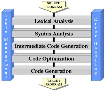
The entire system can be described by describing each of its modules. Each module has a specific task that can be described in a sentence or two. Lexical Analysis partitions the characters of the source input into related groups of characters (reserved words, identifiers, integers, operators) called tokens. The tokens are passed in a stream to Syntax Analysis, which parses the token stream to determine if it is syntactically correct. Syntax Analysis also builds parse trees representing higher level syntactic elements such as expressions and statements. These parse trees are passed to Intermediate Code Generation, which produces a stream of instructions implementing the corresponding statements and expressions in some relatively low level language close to assembly language. This stream of intermediate code is analyzed by Code Optimization to determine if the instructions can be modified in any way to make the resulting code faster and/or smaller. The result is a possibly altered stream of intermediate code that is passed to Code Generation, which will convert the intermediate code instructions into instructions in the target language.
Each of the preceding modules will, at various times, need to deal with symbols (identifier names, labels, etc.) found in the program, adding newly found symbols to a symbol table and also looking up various attributes of symbols that have already been encountered. This service is provided by Table Management. Also, each of the modules may at some point encounter errors in the source program. Lexical Analysis may find an unexpected character or Syntax Analysis may discover a syntax error. When this happens, Error Handling is invoked to inform the user of the error and to initiate recovery mechanisms, adjusting the data flowing through the system so that the compiler can get "back on track" and continue to check the rest of the program for syntax errors, even though generation of operable code may be impossible.
By examining each of the desired attributes of a module described earlier, one can see that this is, indeed, a good modularization of the task.
- Each module is a well-defined subsystem.
- Each module performs a very specific task. For example, Lexical Analysis scans the input for tokens. Table Management allows symbols to be entered into the symbol table and allows attributes of the symbols to be queried.
- Each module is simple enough to understand.
- It is simple enough to understand what each module does. It is probably unclear how some of these modules perform their task, since their task is rather complex. However, through further decomposition of these complex modules, one should be able to understand them completely.
- Each module is independent from the other modules.
- Lexical Analysis is relatively independent from Syntax Analysis, their only interface being that Lexical Analysis provides a stream of tokens to Syntax Analysis. Syntax Analysis is relatively independent from Intermediate Code Generation, their only interface being that Syntax Analysis provides a stream of parse trees to Intermediate Code Generation. All communication between modules is through the passing of well-defined data types.
- Each module's correctness can be determined.
- Again, each module performs a relatively straightforward task that can either be determined correct directly or by determining the correctness of its submodules.
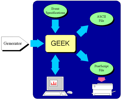
As another example, consider the modular decomposition of GEEK. The highest
level conceptual view of GEEK is shown in Figure 6-3.
The figure shows the main portion of software to be implemented, GEEK, receiving
event information from a Generator. Event count information can be presented
graphically on an X11 display, or it can be dumped to an ASCII file. In
addition, it must be possible to create a PostScript file that represents the
event frequency information graphically, in a manner similar to its display on
the workstation screen. Finally, GEEK must be configurable with respect to the
set of events and their labels at run time through an event specification file.
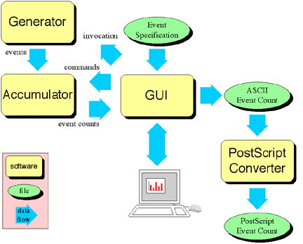
A possible first level modularization of GEEK appears in Figure 6-4.
GEEK has been decomposed into four submodules: Generator,
Accumulator, GUI, and PostScript Converter.
Generator provides a means to invoke a process that can generate events,
outputting a stream of events as they occur. Accumulator continuously
processes a stream of events, counting the number of occurrences of each event
in the stream. It also accepts accumulator commands to reset the event counts,
to start and stop counting events, and to output the current event counts on
request. GUI provides for all interaction with the user, allowing for
specification of the attributes of the events to be collected through an event
specification file, displaying event counts to the user and allowing the user to
control the display and collection of events via an X11 display, and creating
ASCII representations of the event counts. Finally, PostScript Converter
accepts ASCII files representing event counts, producing a PostScript file that
is a graphical representation of those event counts.
How many modules should a typical software system have? There are costs associated with having too many modules; there are also costs associated with having too few. One can consider two costs related to the number of modules in a system -- the cost of development of the module itself and the cost of interfacing that module to other modules in the system. If one has "too many" modules, the cost of the development of each individual module is low, since each module is probably relatively simple; however, due to the large number of modules, the cost of interfacing the modules to each other becomes high. If one has "too few" modules, the cost of the development of each individual module is high, since each module must be relatively complex; however, due to the small number of modules, the cost of interfacing the modules to each other becomes low. Since the total cost associated with the modular decomposition is a function of the cost of development of the modules and the cost of interfacing the modules, the optimum, lies somewhere in between. (This is a somewhat roundabout way of stating that one should be wary of having only a few large modules and of having very many small modules.)
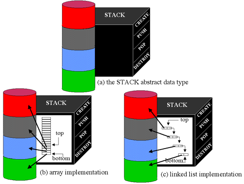
Abstraction is also a very powerful and important design mechanism. It is the separation of the conceptual aspects of a software component from its implementation, thereby reducing the complexity of the issues that must be considered to understand the module and its task. The canonical example of abstraction is the stack abstract data type. The abstraction is that a stack can have the following four operations applied to it:
No other manipulation of the stack is possible. For instance, it is not possible to determine atomically the bottom element of a stack, or to determine atomically the number of elements on a stack. These four operations define the conceptual aspects of a stack. While the stack might very well be implemented as linked lists or arrays of pointers, the implementation of the stack abstraction is not known, is not even considered, and is not important, during design.
There are three basic abstraction mechanisms:
Functional abstraction is abstraction through the use of parameterized functions. The functions can be invoked with different parameters to produce different results. Users of the function need not understand its implementation; they must only understand the meaning of the parameters that must be passed to the function and the meaning of the result returned. A simple example of functional abstraction is a set of functions for computing trigonometric values. All the user needs to know, for instance, is that sin(theta), cos(theta), and tan(theta) return trigonometric functions of radian arguments.
Another example of functional abstraction is a set of functions that performs the operations concatenation, copy, comparison, and length of strings, e.g.
An example of functional abstraction that might be used in a graphical user interface is a set of user interface tools, e.g. a menu tool that can be used to request that the user make a selection from one of a finite set of choices.
GetChoice(string1, string2, ..., stringn)
might have the abstraction of presenting a set of n choices to the user, with choice i labeled with the string stringi. The selection made by the user is returned as a number c in the range [1,n], indicating that the cth choice was selected. It is not known by (and is not important to) the caller of this functional abstraction how the choices are displayed to the user or how the user makes a selection. These details have been "abstracted away."
A second abstraction mechanism is data abstraction. In this mechanism one defines a data type by specifying the set of legal operations allowed on that data type. The stack example above is an example of data abstraction. However, data abstraction need not apply only to simple data structures. Another example of data abstraction is that of a set of graphical objects on a bit-mapped display. A "rectangle" data type might represent a rectangular object that can be created, destroyed, moved, and resized on the display. The operations might be informally described as
- rectangle = CreateRectangle(x, y, w, h)
- Create a rectangle with width w and height h with its upper left corner at location (x, y) on the display. The newly-created rectangle is returned and may be referenced in future rectangle operations.
- MoveRectangle(rectangle, x, y)
- Move the rectangle rectangle so that its upper left corner is at location (x, y). Its width and height are unaffected.
- ResizeRectangle(rectangle, w, h)
- Change the rectangle rectangle to have width w and height h. Its location is unaffected.
- DestroyRectangle(rectangle)
- Destroy the rectangle rectangle and remove it from the display. The rectangle may no longer be referenced.
It is not (and should not be) mentioned how this rectangle facility is implemented. It is only important that when the given operations are applied to a rectangle, the given results will occur.
Data abstraction might be used in a spreadsheet application for the representation of the spreadsheet itself. An abstract view of a spreadsheet data structure might be as a set of rows and columns of cells, whose values are arbitrary expressions, that can be accessed with the following routines:
- PutCell(value, row, column)
- Store the value indicated by value in the cell specified by row and column.
- value = GetCell(row, column)
- Return the value stored in the cell indicated by row and column.
- PutRow(rowvalues, row)
- Store the set of values indicated by rowvalues in the row specified by row.
- rowvalues = GetRow(row)
- Return the set of values stored in the row indicated by row.
- PutColumn(columnvalues, column)
- Store the set of values indicated by columnvalues in the column specified by column.
- columnvalues = GetColumn(column)
- Return the set of values stored in the column indicated by column.
A third abstraction mechanism is control abstraction. Control abstraction is used to state a desired control effect without stating how that effect is achieved. Various control constructs in modern programming languages, such as switch, for, while, if-else, and repeat, are examples of control abstraction. Dijkstra's semaphores used in controlling mutual exclusion are another example. From [Shaw 74],
... These primitives, designated P and V, operate on non-negative integer variables called semaphores. Let S be such a semaphore variable. The operations are defined as follows:If several processes simultaneously call for P or V operations on the same semaphore, these operations will occur sequentially in an arbitrary order; similarly, if more than one process is waiting on a P operation and the affected semaphore becomes positive, the particular waiting process that is selected to complete the operation is arbitrary and unknown.
- V(S): S is increased by 1 in a single indivisible action; the fetch, increment, and store cannot be interrupted, and S cannot be accessed by another process during the operation.
- P(S): Decrement S by 1, if possible. If S == 0, then it is not possible to decrement S and remain in the domain of nonnegative integers; the process invoking the P operation then waits until it is possible. The successful testing and decrementing of S is also an indivisible operation.
This control abstraction separates the conceptual idea of what a semaphore does from its implementation, which may be by various methods in software or even in hardware.
Another example of a control abstraction is Brinch Hansen's concept of a monitor. From [Nutt 92],
A monitor is an abstract data type for which only one process may be executing procedures in the abstract data type at any given time.
The monitor abstract data type appears to the user like any other abstract data type, i.e., as a set of procedures for manipulating the abstraction. However, the monitor control abstraction insures the user that whenever a process executes one of the procedures of the abstraction, that process will be the only process executing one of the procedures of the abstraction. This allows the user to be unconcerned with race conditions with respect to data manipulation within the abstract data type. The user does not need to know and does not care how this control abstraction is implemented.
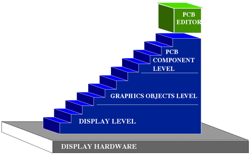
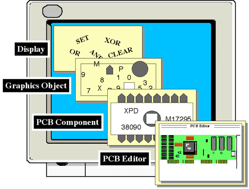
While abstraction is in itself a quite powerful mechanism, this power can be
leveraged through the use of multiple levels of abstraction, each level
building on the abstractions provided by its immediately lower level. For
example, consider the graphical aspects of an interactive printed circuit board
design system. One possible means of providing levels of abstraction is shown in
Figure 6-5.
The lowest level (the Display Level) might provide some abstract way of
viewing the bit-mapped display hardware and operating on the pixels of that
display. The operations might consist of the RasterOps, logical operations (e.g.
AND, OR, XOR, SET, CLEAR) on rectangular regions of pixels. The next level (the
Graphics Objects Level) might provide an abstraction of various objects
that can be drawn on the display -- circles, polygons, lines, and text -- with
varying attributes of location, color, and size. The highest level (the PCB
Component Level) might provide an abstraction of components of a printed
circuit board -- traces, integrated circuits, board layers, pins -- that can be
manipulated on the display.
Given these levels of abstraction, when a user (a programmer) of the PCB
Component Level decides to place an integrated circuit on the display, he or
she does so by merely requesting to the PCB Component Level that an
integrated circuit of the appropriate type be placed at a particular location on
the display. The user does not have to be concerned with how the particular
integrated circuit is drawn. Similarly, when the PCB Component Level
needs to place an integrated circuit on the display, it does so by requesting
that the Graphics Objects Level place various shapes and text (the ones
that combine to form the integrated circuit) on the display, with no knowledge
required of how the Graphics Objects Level actually draws the circles,
polygons, and text. Finally, when the Graphics Objects Level needs to
place an object, e.g. a polygon, it uses the operations provided by the
Display Level to cause the polygon to appear, with no concern as to how
the operations are actually implemented (hardware or software) and how the bits
in video memory are actually set. Through the use of levels of abstraction, the
complex task of drawing an integrated circuit has been reduced from one of being
concerned about which pixels to set (and how to set them) to one of concern
about which components to place on the display and where to place them -- a much
simpler world in which the implementor of the PCB design editor may work. The
levels of abstraction involved in the display of a PCB component are shown in Figure 6-6.
A reduction in complexity is not the only benefit to multiple levels of abstraction. Layering abstractions also leads to increased reusability of the software. The well-defined interface between layers hides the complexity of the lower layers from the upper layers. But this well-defined interface by which a layer uses the layer below it also means that a lower layer has no knowledge of any of the characteristics of any layer above it. Lower layers are, in fact, quite independent of the upper layers. This means that lower layers can be reused in any system that needs the services provided by those layers. This is a strong argument for the development of generalized abstractions.
In addition to reduced complexity and increased reusability, layering of abstractions usually leads to more portable software. In this particular example, the lowest level of abstraction is the only one that knows about hardware details. This implies that the only level that should require modification when porting to new display hardware is the Display Level, the other levels having been built on top of the Display Level, and thus being independent of the actual display hardware.
Information hiding refers to the hiding of the internal design decisions of a module from the world outside that module. A goal is to minimize the impact that changes in the internal design and implementation of a module have on the external world. Information hiding includes both the hiding of internal data representations as well as internal algorithms. The abstraction mechanisms discussed above typically provide good information hiding.
The stack example hides the representation of the stack from the user. Its
internal representation could be changed from an array of pointers to a linked
list of structures with no impact on the user of that abstraction. Even though
its implementation changes, its external interface remains constant (Create,
Push, Pop, Destroy), as shown in Figure 6-7.
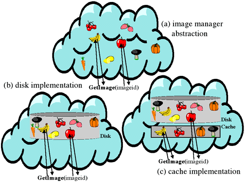
Another example of the use of information hiding might be provided by a
module managing the access of large bitmapped images from disk. The interface to
this module might be one that takes an image identifier, finds the image on the
disk, and loads it into memory. This interface hides the details of what is
actually occurring inside of the module. One possible implementation might be to
simply find the correct image on the disk and read it in each time it is
requested. However, suppose it was later determined that reading in an image was
quite expensive, and that requests to the image access module were often
requests for the same images that were asked for in the recent past. The
implementation might be changed to one that cached recently requested images,
without affecting the interface to the rest of the system. These two
implementations are depicted in Figure Figure 6-8.
The understandability of a design is a measure of the ease with which one can comprehend what the design does and how it does it. Understandable designs are clear and easy to explain. In the compiler modularization provided earlier, the very complex task of compilation was made relatively clear and easy to understand. To be sure, there are many complex details within each module that are left unanswered, but due to the modularization these can be resolved in isolation from the complex details of the other modules.
A concept closely related to understandability is design uniformity. Uniformity implies the lack of inconsistencies and unnecessary differences among various aspects of the design. This applies particularly to the notation and nomenclature used for explaining the components of the design. For example, in describing a module that provides a stack abstraction, one should be consistent in the method of naming the operations allowed on a stack. The operations should not, for example, be described as CreateStack, StackPush, pop_stack, and stkDestroy. These unnecessary differences in naming cause confusion to someone attempting to understand the design. A more consistent naming convention would be CreateStack, PushStack, PopStack, and DestroyStack, or perhaps create_stack, push_stack, pop_stack, and destroy_stack.
Uniformity also applies to the consistency of the operation of components, i.e. operations that are similar should behave similarly. If in a stack module of a generalized list library, stack creation is described as
- stack = CreateStack()
- Creates and returns a new stack.
creation of a queue in a queue module should not be described as
- queue = CreateQueue(maxsize)
- Creates and returns a new queue. The parameter maxsize indicates the maximum number of elements that may be placed in the queue.
Requiring a maximum size for a queue, but not for a stack, is an unnecessary difference. Stack creation and queue creation are two very similar concepts, and they are part of the same library. Either they both should require a maximum size (probably a bad idea), or neither should require a maximum size, but should be able to handle stacks and queues of arbitrary size (probably a good idea).
Reusability is a measure of the application of a software component within systems other than the one for which it was originally designed. Reusability is an important design concept as well as an important design goal. Obviously, if modules are designed to be usable across many applications (a general stack, queue, and list mechanism for instance), productivity can be increased, since the module will not need to be redesigned and reimplemented each time it is needed. However, there is also a side benefit of designing for reusability. It leads to more generalized modules with typically better abstraction. This is due to the fact that designing for reusability usually causes one to dwell less on the specifics of the current problem, and to think more in the abstract terms of the general case.
Change is one of the most difficult problems faced in software development. Goals and requirements typically evolve over the lifetime of a software system. An adaptable design is one which is easy to modify and maintain. Adaptable designs are flexible and relatively impervious to changes. Changes in one part of a good design tend not to propagate to the rest of the design. Adaptability is usually achieved by minimizing coupling and maximizing cohesion. The concepts of coupling and cohesion will be discussed shortly.
The final fundamental design concept is aesthetics. The aesthetics of a design are very difficult to quantify. However, good designs are almost always aesthetically pleasing. Simplicity and elegance are good goals in software design just as they are in many other disciplines. In general, if there is something "ugly" about a design, the design could probably be improved. Poor design decisions are usually reflected as "warts" or "bags on the side."
Since modularization is a good attribute of a software design, it is useful to look at criteria that might be used to guide the decomposition of software into modules. There are two measures of a software design that are useful as modularization criteria. These measures are called coupling and cohesion. They are mentioned briefly below.
Coupling is a measure of the interconnection among the modules of a design.
It indicates the difficulty of changing one module without affecting the other.
Tightly coupled modules might, for instance, have complex interfaces that share
global data. Loosely coupled modules have simple interfaces and no sharing of
data. Coupling is actually a spectrum of values. Common names for points in the
spectrum from highest degree (least desirable) of coupling to the lowest degree
(most desirable) of coupling are shown in Figure 6-9
below.
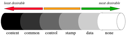
Content coupling exists when one module directly modifies data or (worse) instructions in another module. Common coupling occurs when all modules access a common data structure. Control coupling happens when one module passes flags to another module that control the internal processing of the module. Stamp coupling occurs when there is selective sharing of data structures among only certain modules. Data coupling involves communication only through the passing of arguments. In general, good modularizations tend toward the end of the spectrum that exhibits a low degree of coupling.
Cohesion is a measure of the binding of components within a single module.
Cohesion is also a spectrum of values ranging from the weakest degree of
cohesion (least desirable) to the strongest degree of cohesion (most desirable).
Common names for points on this spectrum are shown in Figure 6-10.
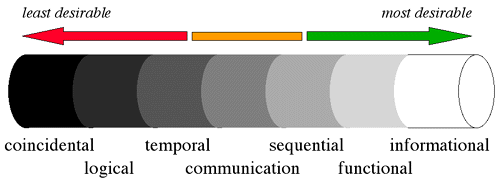
In coincidental cohesion the components of the module have no relationship with one another (other than that they are in the same module!), e.g. a module that computes trigonometric functions, handles keyboard and mouse input, and provides timer interrupts. Logical cohesion occurs when a module performs tasks that are related only logically, e.g. all I/O functionality. A module exhibits temporal cohesion when its tasks are related only in that they are all performed at approximately the same time, e.g. an "initialization" module. These are all relatively low on the cohesion scale.
Moderate levels of cohesion are communication cohesion and sequential cohesion. Communication cohesion occurs when a module performs several tasks on the same set of input and/or output data, e.g. a module to save data on a file and also to print it on a printer. Sequential cohesion occurs when the tasks of a module are related in that they occur one after another in a sequential fashion, e.g. a module that builds a parse tree and generates code from it.
The highest levels of cohesion are functional cohesion and informational cohesion. Functional cohesion occurs when the components of a module work together to perform a single task, e.g. a module to compute the natural logarithm of a number or a module to request a file name from the user. Informational cohesion is exhibited when the components of a module work together to manage some complex data structure, e.g. the functions to manipulate the stack abstract data type.
The quantification of the particular levels of coupling and cohesion in a given design is difficult. Fortunately, it is not important to determine the specific level of coupling and cohesion; it is only important to understand the concepts and realize that, in general, intermodule coupling is minimized and intramodule cohesion is maximized in good designs.
Although coupling and cohesion are the most important modularization criteria, there are others. These include
In an attempt to remove some of the "art" from software design and make it a somewhat more mechanical process, several design methodologies have been developed. These methodologies are actually guidelines that assist in the development of software, and are not magic in themselves. They typically are means to develop software that makes use of the fundamental design principles mentioned earlier.
There are two basic design approaches: top-down and bottom-up. In a top-down
approach, attention is given first to the very highest level of the system and
what it does for the user. This view is then decomposed into simpler components,
which are further decomposed into yet simpler components, until the components
are simple enough that their implementation is straightforward. As an example,
again consider the design of a compiler. A top-down approach might first
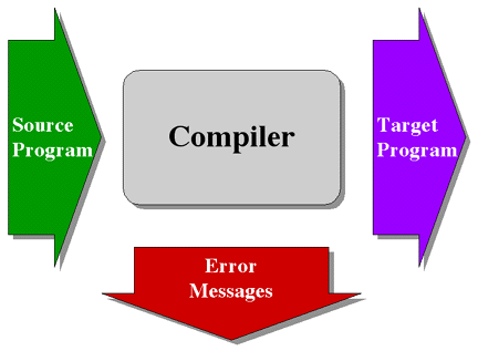
represent the software as a "black box" that receives program source statements
as input and produces target machine object files, and possible error messages,
as output, as shown in Figure 6-11.
The next decomposition might be into three modules, as shown in Figure 6-12:

- Macro Preprocessor
- responsible for accepting a source file containing preprocessor macros in addition to pure source and producing a stream of pure source code.
- Parse Tree Generator
- responsible for accepting a stream of pure source code, determining its syntactical and semantic correctness, and producing a stream of parse trees representing higher level syntactic elements such as expressions and statements.
- Code Generator
- responsible for converting a stream of parse trees into object code in the target language.
Similarly, the Code Generator might then be further decomposed into three
more modules, as shown in Figure 6-13.
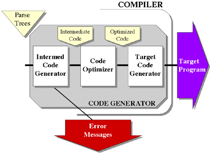
- Intermediate Code Generator
- responsible for accepting a stream of parse trees and generating a stream of instructions implementing the corresponding statements and expressions in some relatively low level language close to assembly language.
- Code Optimizer
- responsible for analyzing the stream of intermediate code to determine if the instructions can be modified in any way to make the resulting code faster and/or smaller, producing a possibly altered and improved stream of intermediate code.
- Target Code Generator
- responsible for converting the stream of intermediate code into instructions in the target language.
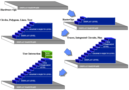
A bottom-up approach first defines the very lowest level of the system, the
"primitives" on which the system is based. Higher levels are built on top of
lower levels until the highest level with the desired properties is created.
This approach might have been used in the development of the printed circuit
board design system used in the discussion of levels of abstraction. The display
primitives might first have been designed, followed by the graphics object
primitives (which use the services provided by the display primitives), followed
by the PCB component primitives (which use the services provided by the graphic
object primitives), and finally followed by the design of the interactive PCB
editor application itself, as shown in Figure 6-14.
Real projects rarely follow either a strict top-down or a strict bottom-up strategy. Both top-down and bottom-up strategies typically involve lots of backtracking. As new levels are designed, it may become apparent that previous levels should be modified. The designers must return to those levels, modify their designs and possibly the designs of levels built on them. However, the basic strategies are good ones to follow.
The various methodologies mentioned below each have application areas in which they are more appropriate than others. Each methodology is typically based on a "top-down" approach, a "bottom-up" approach, or a combination of the two. Several of these techniques will be very briefly mentioned here, along with references for further reading. Other discussions can be found in [IEEE 86] and [ACM 90].
Stepwise refinement, first described in [Wirth 71], is a top-down approach for decomposing a high-level system into successively simpler components. As Fairley [Fairley 85] indicates, it consists of the following activities:
The use of multiple levels of abstraction in design was mentioned previously. It is a bottom-up approach first described by Dijkstra [Dijkstra 68] with respect to the design of the T.H.E. operating system. Each level of abstraction provides a set of services to the higher levels, at the same time hiding internal details of the abstraction.
Structured design, developed by Stevens, Myers, and Constantine [Stevens, Myers, and Constantine 74], is a top-down methodology. It attempts to allow for the systematic conversion of data flow diagrams into structure charts. Measures of cohesion and coupling are used to guide this process.
Jackson Structured Programming was developed by Michael Jackson 2. [Jackson 75] as a systematic technique for mapping the structure of a problem into a program structure to solve the problem. In this technique, tree structured diagrams are used to specify input and output data structures that model the problem. The input-output model is then converted into a structural model for the program. This structural model is then expanded into a detailed design model.
Object-oriented design is a design technique that is gaining considerable popularity and shows significant promise in simplifying the design of complex systems. In object-oriented design, a software system is described as a set of interacting objects, each one able to respond to a particular set of requests. This is in contrast to describing the design as a set of processing functions operating on data, as in functional design. An object is a distinct entity encompassing its own state, along with a set of operations (called methods) that can be performed by the object to manipulate its state. An object can be made to execute one of its methods by sending it a message. Object-oriented design encourages the use of abstraction, information hiding, and modularization to a high degree, which typically leads to low coupling among and high cohesion within modules.
Goldberg and Robson provide a good introduction to object-oriented design with respect to the Smalltalk-80 software system in [Goldberg and Robson 83] that is worth repeating in full:
An object represents a component of the Smalltalk-80 software system. For example, objects representAn object consists of some private memory and a set of operations. The nature of an object's operations depends on the type of component it represents. Objects representing numbers compute arithmetic functions. Objects representing data structures store and retrieve information. Objects representing positions and areas answer inquiries about their relation to other positions and areas.
- numbers
- character strings
- queues
- dictionaries
- rectangles
- file directories
- text editors
- programs
- compilers
- computational processes
- financial histories
- views of information
A message is a request for an object to carry out one of its operations. A message specifies which operation is desired, but not how that operation should be carried out. The receiver, the object to which the message was sent, determines how to carry out the requested operation. For example, addition is performed by sending a message to an object representing a number. The message specifies that the desired operation is addition and also specifies what number should be added to the receiver. The message does not specify how the addition will be performed. The receiver determines how to accomplish the addition. Computing is viewed as an intrinsic capability of objects that can be uniformly invoked by sending messages.
The set of messages to which an object can respond is called its interface with the rest of the system. The only way to interact with an object is through its interface. A crucial property of an object is that its private memory can be manipulated only by its own operations. A crucial property of messages is that they are the only way to invoke an object's operations. These properties insure that the implementation of one object cannot depend on the internal details of other objects, only on the messages to which they respond.
Messages insure the modularity of the system because they specify the type of operation desired, but not how that operation should be accomplished. For example, there are several representations of numerical values in the Smalltalk-80 system. Fractions, small integers, large integers, and floating point numbers are represented in different ways. They all understand the same message requesting the computation of their sum with another number, but each representation implies a different way to compute that sum. To interact with a number or any object, one need only know what messages it responds to, not how it is represented.
. . .
An example of a commonly-used data structure in programming is a dictionary, which associates names and values. In the Smalltalk-80 system, a dictionary is represented by an object that can perform two operations: associate a name with a new value, and find the value last associated with a particular name. A programmer using a dictionary must know how to specify these two operations with messages. Dictionary objects understand messages that make requests like "associate the name Brett with the value 3" and "what is the value associated with the name Dave?" Since everything is an object, the names, such as Brett or Dave, and the values, such as 3 or 30, are also represented by objects. Although a curious programmer may want to know how associations are represented in a dictionary, this internal implementation information is unnecessary for successful use of a dictionary. Knowledge of a dictionary's implementation is of interest only to the programmer who works on the definition of the dictionary object itself.
Objects can be thought of as instances of entities of a new type. Instead of the word "type," the word class is usually used to refer to the type of an object. The word object is used to refer to an instance of the class which specifies the type of the object. The dictionary class refers to entities that have the ability to associate a name with a new value and find the value last associated with a particular name. The dictionary class is an abstract concept. A dictionary object refers to a specific instance of a dictionary -- a particular object that has the properties of a dictionary. This can be compared with the abstract concept of integer, versus the concrete idea of particular instances of an integer, e.g. the integer variables wordcount and exponent.
This section describes three examples of the use of object-oriented design. It also discusses the concept of inheritance, as it applies to object-oriented design, as well as brief comments on choosing objects and the advantages of object-oriented design.
Object-oriented design can be applied to many different types of problems. Three brief examples of the use of object-oriented design -- in a graphics editor, in a compiler, and in hardware control -- are given below.
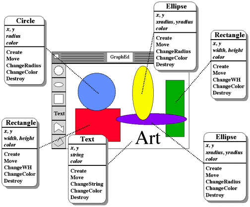
As an example of the use of objects in a design, consider a typical graphics editor which allows one to draw various shapes on the screen to compose a picture. If object-oriented design had been used in this system, one of the classes of objects might very well be Circle. The state of a Circle might include
The methods for the Circle class might include
- Create(x, y, radius, color)
- Create an instance of a Circle with location (x, y), radius radius, and color color.
- Move(x, y)
- Change your location to (x, y).
- ChangeRadius(radius)
- Change your radius to radius.
- ChangeColor(color)
- Change your color to color.
Other classes of objects (for ellipses, rectangles, text, etc.) would have
similar states and operations. The editor manipulates objects on the screen by
creating instances of the object class and sending messages to them to cause
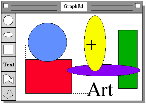
them to do the things that the user requests. Figure Figure 6-15
shows the editor screen face and the instances of shape objects on the screen
along with their associated operations.
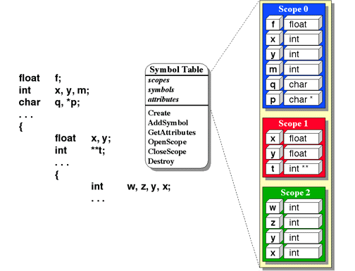
In the example above, an object was something with a visual representation. This need not always be the case. Consider an object-oriented approach in the design of a compiler. A class that might be used in this design might be a symbol table class. A SymbolTable would include an entry for each symbol defined in the table along with its attributes. It would also include a means for managing nested scope, so that referencing identifier name refers to the identifier with name name in the innermost active scope in which it is defined. The state of the SymbolTable object would include a set of symbols, the attributes associated with the symbol, and an indication as to which scope the symbol belonged. The methods defined for this class might include
- Create()
- Create a new instance of a SymbolTable, with an empty current scope.
- AddSymbol(symbol, attributes)
- Add the symbol symbol with attributes attributes to the current scope.
- GetAttributes(symbol)
- Return the attributes of the symbol symbol (the one defined in the innermost scope).
- OpenScope()
- Create a new scope, nested within the current scope.
- CloseScope()
- Destroy the current scope and remove all of its symbols, making the innermost containing scope the new current scope.
This SymbolTable class might be used in a C compiler in the following
manner. When the compiler starts processing a file, it creates an instance of a
SymbolTable (sends the Create message 3).
As the compiler encounters new definitions of symbols, it adds them to the
symbol table by sending the AddSymbol message, along with the appropriate
arguments, to the SymbolTable. As it encounters references to symbols, it
sends the GetAttributes message to the SymbolTable to determine
what the symbol references (an int, a char, or a function
returning a float, for instance). As left curly braces are encountered,
OpenScope messages are sent to the SymbolTable to indicate that
any new symbols are to be defined in a nested scope. As right curly braces are
encountered, CloseScope messages are sent to the SymbolTable to
indicate that the nested scope has been left and any symbols defined in that
scope should be deleted. This is shown graphically in Figure 6-16.
As one final example of object-oriented design, consider a design for a
software factory control system in which the software objects are associated
with physical objects. The factory might contain various pieces of hardware
(pumps, valves, and environmental monitors, such as temperature and pressure
sensors). The software system could be viewed as controlling a set of
Pump, Valve, and Monitor objects. A Pump class might
have methods for Start, Stop, and Status, a Valve class might have
methods for Open, Close, and Status, and a Monitor class might have only
a Read method to get the current value. The system runs the factory by sending
messages to the various software objects, which, in turn, cause their
corresponding physical objects to behave appropriately (valves to open, pumps to
start, pressure sensors to report the pressure). This is shown graphically in Figure 6-17.

Although not strictly a necessary part of object-oriented design, the notion of inheritance of one class from another can play a significant role in the design of object-oriented systems. To say that a class B inherits from a class A means that an instance of an object of type B has all of the properties (methods) of an instance of an object of type A, and possibly some additional properties defined only for objects of type B. (This means that objects of type B are objects of type A, but objects of type A are not objects of type B.)
By applying inheritance recursively, type hierarchies can be produced. These kinds of hierarchies appear in the world around us. For example, consider the class of things called plants. All plants share a common set of properties -- they are all life forms that are green and can synthesize their own food using light energy 4. A tree is a plant that has some additional properties -- it has a woody stem eight feet or more in height with a crown of branches and leaves at the top. An oak is a tree with yet more special properties -- it has a thick trunk and large, wide-spreading branches, deeply lobed leaves, and produces fruit in the form of a round nut in a wood cap. However, a plant is not necessarily a tree, and a tree is not necessarily an oak.
As an example of how inheritance might be used in an object-oriented software
design, consider the design of a graphical editor similar to the one used in
earlier examples. This editor allows the user to create diagrams by drawing (and
erasing) various graphical entities on the screen. These graphical entities, and
their corresponding attributes, are shown in Figure 6-18.
A line can be represented by the coordinate of its source endpoint, the relative
offset of its destination endpoint from its source, and its color. A rectangle
requires the coordinate of its lower left corner, its width and height, and its
color. The attributes of an ellipse are the coordinate of its center, its x and
y radii, and its color. Finally, text can be represented by the coordinate of
its leftmost character, its font type, the string to be displayed, and its
color.

What set of classes might one use in an object-oriented design of this system? The first guess is obvious; the classes would be Line, Rectangle, Ellipse, and Text. However, upon further observation, we might determine that a type hierarchy could be developed.
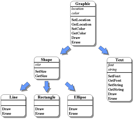
First, we might notice that each of these entities has at least one attribute in common -- color. Upon further analysis, we realize that each entity has to be drawn some place; it has a location represented by an (x,y) coordinate. For a Line, its location can determined by its source endpoint. The location of a Rectangle is the coordinate of its lower left corner. An Ellipse has the coordinate of its center as its location. And finally, the location of a Text object is the coordinate of its leftmost character. This might lead us to create a class, called Graphic, which contains these common attributes, methods to change them and determine their current values, and, of course, methods to draw and erase the graphic entity itself. This might be represented in very pseudo-C++ as follows:
class Graphic
	private:
		Coordinate	location
		Color		color
	public:
		void		SetLocation(x, y)
		Coordinate	GetLocation()
		void		SetColor(color)
		Color		GetColor()
		void		Draw()
		void		Erase()
We have defined a class of object called Graphic. It has internal (private) state, consisting of the location and color of the Graphic, which only it can manipulate. Since only the Graphic itself can read and modify this state directly, it provides a set of methods to allow the outside world to read and modify its location and color in a controlled way, without any knowledge of exactly how this location and color are represented internally. Finally, it provides methods for both drawing and erasing the graphic 5. This defines the first level of our type hierarchy.
The next step in the development of the type hierarchy might be to simply make Line, Rectangle, Ellipse, and Text subclasses of Graphic and be done with it. But closer examination reveals that there might be some commonality among the classes Line, Rectangle, and Ellipse -- they all have some concept of "size", which can be represented by an (x,y) pair (a coordinate). The size of a Line is indicated by a pair specifying the horizontal and vertical offset of the destination endpoint from the source endpoint of the line. The size of a Rectangle is given by a pair specifying its width and height, while the size of an Ellipse is indicated by a pair representing the x and y radii of the ellipse. Thus, we might define a subclass of Graphic, called Shape, whose very pseudo-C++ might appear as follows:
class Shape is subclass of Graphic
	private:
		Coordinate	size
	public:
		void		SetSize(xdim, ydim)
		Coordinate	GetSize()
We now have a class of object whose size can be manipulated (since it is a Shape), and whose color and location can be manipulated (since it is a Graphic). It can also be drawn and erased (since it is a Graphic). But drawing and erasing a Graphic has no effect; we need lines, rectangles, and ellipses.
We are now at the point in the development of the type hierarchy where there is really nothing left in common among the classes Line, Rectangle, and Ellipse. All of their attributes are included in the class Shape, either directly or by inheritance from Graphic. The only remaining characteristic is exactly how they are drawn, which is certainly different for each entity. The classes Line, Rectangle, and Ellipse can then be defined as subclasses of Shape, each subclass defining draw and erase routines particular to its graphic entity. This might be represented in very pseudo-C++ as follows:
class Line is subclass of Shape
	public:
		void	Draw()
		void	Erase()
class Rectangle is subclass of Shape
	public:
		void	Draw()
		void	Erase()
class Ellipse is subclass of Shape
	public:
		void	Draw()
		void	Erase()
Notice that none of these subclasses need any private data. They only require their specialized drawing and erasing routines.
But what about Text? Since, as it is defined in this system, text does not have the attribute of size, it cannot be a subclass of Shape. However, it does have location and color, so it can simply be made a subclass of Graphic, as shown below:
class Text is subclass of Graphic
	private:
		Font		font
		String		string
	public:
		void		SetFont(font)
		Font		GetFont()
		void		SetString(string)
		String		GetString()
		void		Draw()
		void		Erase()
The class Text has private data to represent the font and the string
of characters to be used when it is drawn and erased. It also includes methods
for reading and modifying the font and string, and, of course, methods for
actually drawing and erasing the text itself. The completed type hierarchy is
shown in Figure 6-19.
This example is based on existing visual objects (classes of graphical shapes) which have specific existing attributes and relationships. However, this same kind of approach can be applied to create type hierarchies of more abstract objects, such as list-like data structures (stacks, queues, sorted lists), communications interfaces (packets, messages, protocols), and many other object classes.
Inheritance is supported by most object-oriented languages. It can play a significant role in leveraging the power of an object-oriented design in much the same way that layers of abstraction leverage the power of the general notion of abstraction.
How does one know what objects to define in a particular object-oriented design? Unfortunately, there is no precise algorithm that will lead to the optimal design for any given problem. However, some insight into this issue can be found in [Goldberg and Robson 83]:
An important part of designing Smalltalk-80 programs is determining which kinds of objects should be described and which message names provide a useful vocabulary of interaction among these objects. A language is designed whenever the programmer specifies the messages that can be sent to an object. Appropriate choice of objects depends, of course, on the purposes to which the object will be put and the granularity of information to be manipulated. For example, if a simulation of an amusement park is to be created for the purpose of collecting data on queues at the various rides, then it would be useful to describe objects representing the rides, workers who control the rides, the waiting lines, and the people visiting the park. If the purpose of the simulation includes monitoring the consumption of food in the park, then objects representing these consumable resources are required. If the amount of money exchanged in the park is to be monitoried, then details about the cost of rides have to be represented.
In designing a Smalltalk-80 application, then, choice of objects is the first key step. There really is nothing definitive to say about the "right way" to choose objects. As in any design process, this is an acquired skill. Different choices provide different bases for extending an application or for using the objects for other purposes. The skilled Smalltalk-80 programmer is mindful that the objects created for an application might prove more useful for other applications if a semantically complete set of functions for an object is specified. For example, a dictionary whose associations can be removed as well as added is generally more useful than an add-only version.
While there is no definitive algorithm for choosing the right objects, Pressman [Pressman 92] does provide some guidelines for a set of simple steps that assists that process:
- 1. Identify the data abstractions for each subsystem.
- These data abstractions are the classes for the system. Working from the requirements document, the abstraction process should be performed top-down when possible, although many times the abstractions are mentioned explicitly in the requirements. Often the classes correspond to physical objects within the system being modeled. If this is not the case, the use of analogies, drawn from the designer's experience on past system designs, is helpful. This is, by far, the most difficult step in the design process and the selection of these abstractions influences the entire system architecture.
- 2. Identify the attributes for each abstraction.
- The attributes become the instance variables ... for each class. Many times, if the classes correspond to physical objects, the required instance variables are obvious. Other instance variables may be required to respond to requests from other objects in the system. Defer the specification of the data structures containing the attributes until the detail design stage.
- 3. Identify the operations for each abstraction.
- The operations are the methods (or procedures) for each class. Some methods access and update instance variables, while others execute operations singular to the class. Do not specify the details of the methods' implementations now, only the functionalities. If the new abstraction inherits from another class, inspect the methods of that class to see if any need to be overridden by the new class. Defer the internal design of methods until the detail design stage, where more conventional design techniques can be used.
- 4. Identify the communication between objects.
- This step defines the messages that objects send to each other. Here, define a correspondence between the methods and the messages that invoke the methods. Even if an object-oriented implementation is not planned, messages help the design team to communicate and can be used in the next step to write scenarios. The design team decides on this protocol with consistency in message naming as a primary consideration.
- 5. Test the design with scenarios.
- Scenarios, consisting of messages to objects, test the designer's ability to match the system's requirements specification.
- 6. Apply inheritance where appropriate.
- If the data abstraction process in step 1 is performed top-down, introduce inheritance there. However, if abstractions are created bottom-up (often because the requirements directly name the abstractions), apply inheritance here, before going to another level of abstraction. The goal is to reuse as much of the data and/or methods that have already been designed as possible. At this step, common data and operations often surface and these common instance variables and methods can be combined into a new class. This class may or may not have meaning as an object by itself. Its sole purpose is to collect common instance variables and methods; it is called an abstract class.
Finally, an entire book dedicated to object-oriented analysis can be found in [Coad and Yourdon 90].
Sommerville [Sommerville 89] summarizes the advantages of object-oriented design as follows:
A good discussion of object-oriented design can be found in [Sommerville 89] and [Ghezzi, Jazayeri, and Mandrioli 91]. Booch devotes an entire text [Booch 91] to object-oriented design. Discussions of object-oriented programming and object-oriented languages can be found in [Cox 86] (Objective C), [Goldberg and Robson 83] (Smalltalk-80), [Meyer 92] (Eiffel), [Stroustrup 86] (C++), and [Gosling, Joy, and Steele 96] (Java).
The design of the user interface for a software system, while certainly a very different task than the design of the underlying software, is still one of the most important aspects of a good design. This section first discusses various types of users, followed by a discussion of the primary methods of human-computer interaction. Finally, a number of user interface design guidelines are presented.
If an effective user interface is to be provided, it is necessary for the designer to understand the nature of the users of the system. Shneiderman [Shneiderman 92], separates users into three categories: novice or first-time users, knowledgeable intermittent users, and expert frequent users. He describes varying goals in designing user interfaces appropriate to each category:
- Novice or first-time users:
- The first user community is assumed to have no syntactic knowledge about using the system and probably little semantic knowledge of computer issues. Whereas first-time users know the task semantics, novices have shallow knowledge of the task and both may arrive with anxiety about using computers that inhibits learning. Overcoming these limitation is a serious challenge to the designer. Restriction of vocabulary to a small number of familiar, consistently used terms is essential to begin developing the user's knowledge of the system. The number of possibilities should be kept small, and the novice user should be able to carry out a few simple tasks to build confidence, to reduce anxiety, and to gain positive reinforcement from success. Informative feedback about the accomplishment of each task is helpful, and constructive, specific error messages should be provided when errors do occur. Carefully designed paper manuals and step-by-step online tutorials may be effective. Users are attempting to relate their existing knowledge to the task objects and actions in the application, so distractions with computer concepts and the syntax are an extra burden.
- Knowledgeable intermittent users:
- Many people will be knowledgeable but intermittent users of a variety of systems. They will be able to maintain the semantic knowledge of the task and the computer concepts, but they will have difficulty maintaining the syntactic knowledge. The burden of memory will be lightened by simple and consistent structure in the command language, menus, terminology, and so on, and by the use of recognition rather than recall. Consistent sequences of actions, meaningful messages, and frequent prompts will all help to assure knowledgeable intermittent users that they are performing their tasks properly. Protection from danger is necessary to support relaxed exploration of features or attempts to invoke a partially forgotten command. These users will benefit from online help screens to fill in missing pieces of syntactic or computer semantic knowledge. Well-organized reference manuals will also be useful.
- Expert frequent users:
- The expert "power" users are thoroughly familiar with the syntactic and semantic aspects of the system and seek to get their work done rapidly. They demand rapid response times, brief and less distracting feedback, and the capacity to carry out actions with just a few keystrokes or selections. When a sequence of three or four commands is performed regularly, the frequent user is eager to create a macro or other abbreviated form to reduce the number of steps. Strings of commands, shortcuts through menus, abbreviations, and other accelerators are requirements.
There are a number of different methods of human-computer interaction. A single software system may make use of multiple methods, depending on the user and the tasks to be accomplished. Shneiderman describes five primary styles of human-computer interaction: menu selection, form fillin, command language, natural language, and direct manipulation. Examples of each are given in the figures.
Menu selection. ( Figure 6-20 ) In menu-selection systems, the users read a list of items, select the one most appropriate to their task, apply the syntax to indicate their selection, confirm the choice, initiate the action, and observe the effect. If the terminology and meaning of the items are understandable and distinct, then the users can accomplish their task with little learning or memorization and few keystrokes. The greatest benefit may be that there is a clear structure to decision making, since only a few choices are presented at a time. This interaction style is appropriate for novice and intermittent users and can be appealing to frequent users if the display and selection mechanisms are rapid.
For designers, menu-selection systems require careful task analysis to ensure that all functions are supported conveniently and that terminology is chosen carefully and used consistently. Dialog-management tools to support menu selection are an enormous benefit in ensuring consistent screen design, validating completeness, and supporting maintenance.
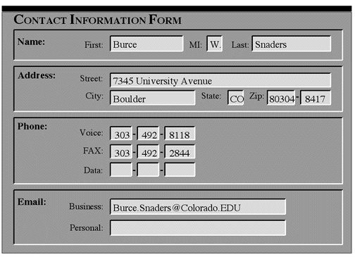
Form fillin. ( Figure 6-21 ) When data entry is required, menu selection usually becomes cumbersome, and form fillin (also called fill-in-the-blanks) is appropriate. Users see a display of related fields, move a cursor among the fields, and enter data where desired. With the form fillin interaction style, the users must understand the field labels, know the permissible values and the data-entry method, and be capable of responding to error messages. Since knowledge of the keyboard, labels, and permissible fields is required, some training may be necessary. This interaction style is most appropriate for knowledgeable intermittent users or frequent users.
Command language. For frequent users, command languages provide a strong feeling of locus of control and initiative. The users learn the syntax and can often express complex possibilities rapidly, without having to read distracting prompts. However, error rates are typically high, training is necessary, and retention may be poor. Error messages and online assistance are hard to provide because of the diversity of possibilities plus the complexity of mapping from tasks to computer concepts and syntax. Command languages and lengthier query or programming languages are the domain of the expert frequent users who often derive great satisfaction from mastering a complex set of semantics and syntax.% ls -lg lastnames ---------- 1 sanders research 45 Sep 9 15:20 lastnames % chmod 444 lastnames % cat lastnames gabow ehrenfeucht winklmann fosdick grunwald % foreach n (`sort lastnames `) ? da -l $n | grep 'email:' | sed -e "s/email:/${n}:/" ? end ehrenfeucht: Andrzej.Ehrenfeucht@Colorado.EDU fosdick: Lloyd.Fosdick@Colorado.EDU gabow: Harold.Gabow@Colorado.EDU grunwald: Dirk.Grunwald@Colorado.EDU winklmann: Karl.Winklmann@Colorado.EDU %
Natural language. The hope that computers will respond properly to arbitrary natural-language sentences or phrases engages many researchers and system developers, in spite of limited success thus far. Natural-language interaction usually provides little context for issuing the next command, frequently required clarification dialog , and may be slower and more cumbersome than the alternatives. Still, where users are knowledgeable about a task domain whose scope is limited and where intermittent use inhibits command-language training, there exist opportunities for natural-language interfaces.User: What's this big green part by the axle? Computer: Which axle, front or rear?
User: Front axle. Computer: What do you mean by big?
User: Roughly 1 foot by 1 foot. Computer: There are no rough parts of that size. There is a smooth part 11.5 in by 11.25 in by 11.75 in. Is that possibly it?
User: Yes. Computer: There are no smooth green parts of that size. There is a smooth chartreuse part. Is that possibly it?
User: Forget it. Computer: Ready for your next request.
Direct manipulation. ( Figure 6-22 ) When a clever designer can create a visual representation of the world of action, the users' tasks can be greatly simplified because direct manipulation of the objects of interest is possible. Examples of such systems include display editors, LOTUS 1-2-3, air-traffic control systems, and video games. By pointing at visual representations of objects and actions, users can carry out tasks rapidly and observe the results immediately. Keyboard entry of commands or menu choices is replaced by cursor-motion devices to select from a visible set of objects and actions. Direct manipulation is appealing to novices, is easy to remember for intermittent users, and, with careful design, can be rapid for frequent users.
Shneiderman contrasts the advantages and disadvantages of these five interaction styles, as shown in Table 6-1 below.
| Advantages | Disadvantages | |
|---|---|---|
| menu selection |
· shortens learning · reduces keystrokes · structures decision making · permits use of dialog-management tools · allows easy support of error handling |
· imposes danger of many menus · may slow frequent users · consumes screen space · requires rapid display rate |
| form fillin |
· simplifies data entry · requires modest training · makes assistance convenient · permits use of form-management tools |
· consumes screen space |
| command language |
· is flexible · appeals to "power" users · supports user initiative · is convenient for creating user-defined macros |
· has poor error handling · requires substantial training and memorization |
| natural language |
· relieves burden of learning syntax | · requires clarification dialog · may require more keystrokes · may not show context · is unpredictable |
| direct manipulation |
· presents task concepts visually · is easy to learn · is easy to retain · allows errors to be avoided · encourages exploration · permits high subjective satisfaction |
· may be hard to program · may require graphics display and pointing devices |
He also provides significantly more discussion, which is well worth reading, devoting entire chapters to each style.
Designing a good user interface is somewhat of an art form. However, there are generally accepted guidelines that can assist the designer in producing a better interface. While they cannot guarantee a good user interface, following these guidelines is almost always an improvement over any corresponding interface that does not follow them.
Pressman [Pressman 92] presents three categories of user interface guidelines: general interaction, information display, and data input. These are summarized below.
Shneiderman [Shneiderman 92] also provides a set of user interface guidelines. These are described as the "Eight Golden Rules of Dialog Design".
- 1. Strive for consistency.
- This principle is the most frequently violated one, and yet is the easiest one to repair and avoid. Consistent sequences of actions should be required in similar situations; identical terminology should be used in prompts, menus, and help screens; and consistent commands should be employed throughout. Exceptions, such as no echoing of passwords or confirmation of the DELETE command, should be comprehensible and limited in number.
- 2. Enable frequent users to use shortcuts.
- As the frequency of use increases, so do the user's desires to reduce the number of interactions and to increase the pace of interaction. Abbreviations, special keys, hidden commands, and macro facilities are appreciated by frequent knowledgeable users. Shorter response times and faster display rates are other attractions for frequent users.
- 3. Offer informative feedback.
- For every operator action, there should be some system feedback. For frequent and minor actions, the response can be modest; whereas for infrequent and major actions, the response should be more substantial. Visual presentation of the objects of interest provides a convenient environment for showing changes explicitly.
- 4. Design dialogs to yield closure.
- Sequences of actions should be organized into groups with a beginning, middle, and end. The informative feedback at the completion of a group of actions gives the operators the satisfaction of accomplishment, a sense of relief, the signal to drop contingency plans and options from their minds, and an indication that the way is clear to prepare for the next group of actions.
- 5. Offer simple error handling.
- As much as possible, design the system so the user cannot make a serious error. If an error is made, the system should detect the error and offer simple, comprehensible mechanisms for handling the error. The user should not have to retype the entire command, but rather should need to repair only the faulty part. Erroneous commands should leave the system state unchanged, or the system should give instructions about restoring the state.
- 6. Permit easy reversal of actions.
- As much as possible, actions should be reversible. This feature relieves anxiety, since the user knows that errors can be undone; it thus encourages exploration of unfamiliar options. The units of reversibility may be a single action, a data entry, or a complete group of actions.
- 7. Support internal locus of control.
- Experienced operators strongly desire the sense that they are in charge of the system and that the system responds to their actions. Surprising system actions, tedious sequences of data entries, incapacity or difficulty in obtaining necessary information, and the inability to produce the action desired all build anxiety and dissatisfaction. Gaines (1981) captured part of this principle with his rule avoid acausality and his encouragement to make users the initiators of actions rather than the responders.
- 8. Reduce short-term memory load.
- The limitation of human information processing in short-term memory (the rule of thumb is that humans can remember "seven plus or minus two chunks" of information) requires that displays be kept simple, multiple page displays be consolidated, window-motion frequency be reduced, and sufficient training time be allotted for codes, mnemonics, and sequences of actions. Where appropriate, online access to command-syntax forms, abbreviations, codes, and other information should be provided.
We will be producing two design documents in this class. The first document will be a description of the high-level system architecture of our software, while the second will be a more detailed specification of the design. The system architecture description is intended to be a somewhat less formal document, lying somewhere between an actual specification and a "back of the envelope" design. The goal is to produce a relatively quick high-level design of our system, from which we are able to begin to do some prototyping. The system architecture is not necessarily expected to be the final, immutable architecture, but rather a place from which to begin. Through prototyping, we hope to be able to advance toward a more thorough and complete design.
The system architecture description document should include a cover page, a problem statement, a table of contents, and an introduction to the project and the paper, as well as the description of the architecture itself. The cover page, problem statement, table of contents, and introduction should follow the same guidelines as in your initial requirements. The introduction should largely be the same as you used for your initial requirements, modified, of course to introduce the topic of this paper. The architectural description should contain a discussion of both the user interface and the high-level modular decomposition of the problem.
If the project has a graphical user interface, sample screen faces would be shown, describing the layout and how the user would interact with the system. If the project has a program interface, as a library might have, then that program interface should be described. This would typically be done as a description of the set of functions, and their corresponding parameters, that make up the interface.
The high-level modular decomposition of the problem should include a figure depicting the decomposition. It should also include a description of each module's external interfaces, the task each module performs, and a description of any input and output data. This should apply to both functional and object-oriented designs.
Following is a checklist of items to be included in your system architecture description.
An example system architecture description for our hypothetical GEEK project can be found below.
Each team will be asked to give an overview presentation on its project. This presentation should be about 30-35 minutes long and will be given in class during the semester. The presentation should be an explanation of what your project is all about, an overview of the requirements, and a description of the system architecture. This section provides some guidelines for use in the preparation and delivery of your talk. It discusses the overall content of the presentation, organizational issues, slide construction hints, and some tips on delivery. Examples from the GEEK project will be used.
Your presentation should include some sort of introduction to the project,
such as the title of your project, its code name (and why you chose it), and who
the team members are ( Figure 6-23
).
Also provide background information on the sponsor, such as their
location(s), how big the company is (in terms of number of employees and/or
revenue), what their primary business is, and their relation to other companies
( Figure 6-24
).
Briefly describe the problem that exists and the proposed solution ( Figure 6-25,
Figure 6-26,
and Figure 6-27
).


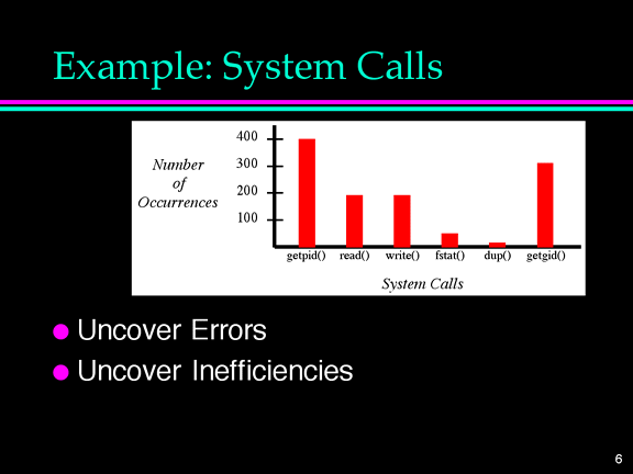
You may need to describe some existing systems to do this. You should also
describe how your project relates to other software and systems through a
conceptual diagram ( Figure 6-28
).
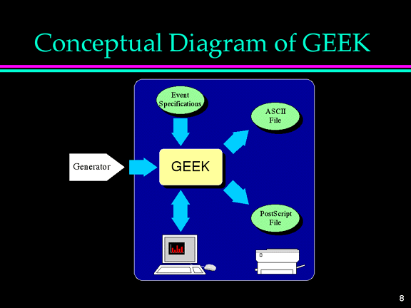
It is useful to mention some of the major requirements, particularly the
environmental ones ( Figure 6-29
).
Finally, include a picture and brief discussion of any user interfaces ( Figure 6-30
).
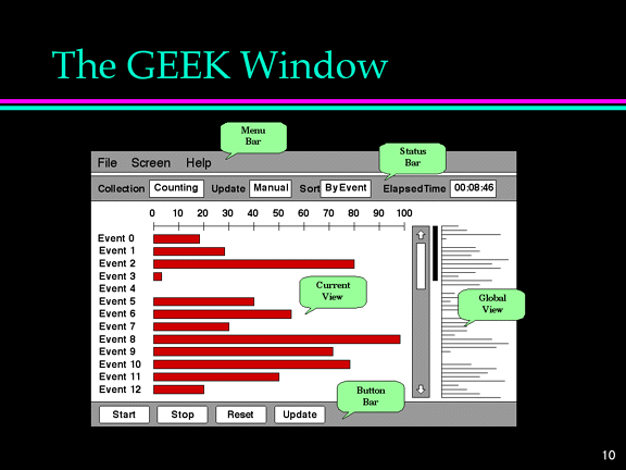
and of your system architecture ( Figure 6-31
).
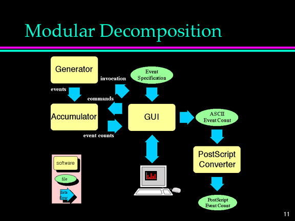
In addition to the basic content of the talk, there are several mechanisms you should use to make sure that your talk flows smoothly, fits together logically, and does not lose the audience. These techniques include the use of effective redundancy, internal summaries, and smooth transitions from one component of the presentation to the next.
In general, you don't want to repeat a topic in your presentation that has already been covered earlier in the presentation. However, the use of redundancy in the talk can help tie the presentation together, enabling the audience to see where you are going with the talk, and at the end to more clearly understand what you have said. A good motto for any presentation is
Tell 'em what you're gonna tell 'em...
Tell 'em...
Tell 'em what you told 'em.
For instance, in the GEEK presentation, after the introductory information is
given, we might have a slide that gives an overview of the major topics of the
talk ( Figure 6-32
).
This lets the audience know what you plan to cover in the talk. We then cover
the material, and at the end of the talk, summarize what was said. This ties the
talk together and helps the audience to remember the main points of the talk (
Figure 6-33
).

It is also helpful to summarize what you have said at various points in your
presentation. For instance, you can put up the overview slide showing the three
main topics that are the focus of the talk ( Figure 6-34
),
and then talk about the first topic -- Introduction to Data Whacker, Inc. Once the first topic has concluded, you can put up the overview slide again, and then introduce the second topic. A good way to do this might be to say
We have given you an introduction to our sponsor. Now we want to talk about the problem they were facing -- Software Optimization.
Then, after talking about the second topic, the overview slide would be put up yet again to introduce the third topic -- The Solution: GEEK.
These internal summaries help to orient the audience to where you are in the talk. If anyone has gotten lost, it helps to get them back on track. This technique is most useful in longer talks. It can be useful at times in shorter talks, but you need to make sure it actually helps the audience and does not become tedious, i.e. use it for the higher levels of the outline of the talk.
Finally, you should try to provide smooth transitions from one slide (or point) to the next. In a well-organized talk, the audience will often be able to guess what the topic of the next slide will be before you even put it up. They should almost never be surprised by the next slide when you put it up. To make this more likely, you should end your discussion of one slide with some transition to the topic on the next slide. For example, the transition from the "problem" slide to the "solution" slide for GEEK might have been something like
To summarize the problem we are faced with: the market is very competitive; one way to compete is with optimized software, and we needed a tool to help us do that. That brings us to the proposed solution -- GEEK. (now put up the next slide)
There are several guidelines that can help in creating good slides for a talk.
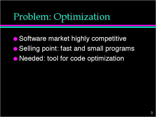
When actually giving the presentation, there are a few problems that come up frequently in talks. Here are some tips that help to avoid them.
It is not required that each person in the group actually give part of the presentation. You should do whatever makes for the best presentation. However, everyone should work on its preparation. A set of overview presentation slides for our example project is included at the end of this section.
Following is a checklist to use in the preparation of your presentation:
An example overview presentation for our hypothetical GEEK project can be found below.
Here is another gem from an unknown author on the habits of programmers.
REAL PROGRAMMERS DON'T EAT QUICHE
(They Can't Even Spell Quiche)
Real Programmers....
Don't eat quiche. Real programmers don't even know how to spell quiche. They like Twinkies, Coke, and palate-scorching Szechwan food.
Don't write applications programs. They program right down to the bare metal. Applications programs are for dullards who can't do systems programming.
Don't comment their code. If it was hard to write, it should be hard to understand and even harder to modify.
Don't draw flowcharts. Flowcharts are, after all, the illiterate's form of documentation. Cavemen drew flowcharts; look how much it did for them.
Don't use COBOL. COBOL is for wimpy applications programmers.
Don't use FORTRAN. FORTRAN is for wimpy engineers who wear white socks, pipe stress freaks, and crystallography weenies. They get excited over finite state analysis and nuclear reactor simulation.
Don't use LOGO. In fact no programmers use LOGO after puberty.
Don't use APL, unless the whole program can be written on one line.
Don't use LISP. Only effeminate programmers use more parentheses than actual code.
Don't use Pascal, BLISS, Ada or any of those sissy-pinko computer science languages. Strong typing is a crutch for people with weak memories.
Never work 9 to 5. If any real programmers are around at 9 a.m., it's because they were up all night.
Don't play tennis or any other sport that requires a change of clothes. Mountain climbing is OK though, and real programmers often wear climbing boots to work in case a mountain should suddenly spring up in the middle of the machine room.
Don't like the team programming concept. Unless, of course, they are the Chief Programmer.
Have no use for managers. Managers are a necessary evil. Managers are for dealing with personnel bozos, bean counters, senior planners, and other mental defectives.
Don't drive clapped-out Mavericks. They prefer BMWs, Lincolns, or pick-up trucks with floor shifts. Fast motorcycles are highly regarded.
Like vending machine popcorn. Coders pop it in the microwave oven. Real programmers use the heat given off by the CPU. They can tell what job is running just by listening to the rate the corn is popping.
Know every nuance of every instruction and use them all in every real program. Puppy architects won't allow execute instructions to address another execute as the target instruction. Real programmers despise such petty restrictions.
Don't bring brown bag lunches to work. If the vending machine sells it, they eat it. If the vending machine doesn't sell it, they don't eat it. Vending machines don't sell quiche.
1 I hesitate to call them fads, but that might not be an inappropriate tag for some of them -- the Macarena of software engineering.
2 No, not that Michael Jackson.
3 What object do we send the Create message to? Creation of an instance of a class is usually a special case. The message can be thought of as being sent to the class to cause the generation of a new instance of an object of that class.
4 This definition of plant is certainly not precise enough for a botanist, but then, this isn't a Botany class.
5 How does one draw and erase an entity that has a location and a color, but does not have any kind of "shape"? By doing nothing.
6 I personally have to be careful on this one. I can't stand still and talk. But if I don't watch out, I'll start moving around all over the place.