INFORMATION
& COMPUTER SCIENCE DEPARTMENT, KFUPM
SWE344:
Internet Protocols & Client-Server Programming
LAB #04: IP Addresses & Network Traffic Monitoring
![]()
Objectives:
·
Learn about IP Addresses and Ports
·
Learn about TCP, UDP and IP headers
·
Learn how to watch and decode IP packets on a network
·
Learn how to find IP address of a host
1.
IP Addresses
Every
node (host or router) on the Internet has a unique
IP address, which is used to identify it.
In
IPv4, each address consists of 32 bits, which is divided into two components –
the network and host component, depending on its class:
![]() However, for readability, IPs are normally written in dotted decimal format (8 bits at a
time, separated by a dot).
However, for readability, IPs are normally written in dotted decimal format (8 bits at a
time, separated by a dot).
For
even more readability, IPs are mapped into symbolic names called domain names.
![]()
As
can be seen from the example, the domain names are organized hierarchically. The mapping data is distributed, where by each
domain is required to have a dedicated machine called the Domain Name Server
(DNS) which keeps records about the nodes in that domain and addresses of
the DNS servers of its sub-domain.
2.
Ports
Generally,
a node has a single physical connection to a network (example, via its network
card).
For
the Internet network (using TCP/IP) protocol, The IP address discussed
earlier is mapped to this physical connection.
All
data destined for this node arrives through this one physical connection.
Now,
since there could be many network applications running, a good question is, how
does the node knows which application a particular packet of data belongs to?
The
answer is, by looking at the port number in that packet. Each packet of data sent over the Internet has
at least two pieces of addressing information, as follows:
The
32-bit IP address uniquely identifies the computer for which the message is
intended, and the 16-bit port number identifies which application the data
should be sent to.
 Hence we have:
Port
numbers range from 0 to 65,535 (i.e. a 16 bit value).
It
is important that your programs do not use port number 0 to 1023 as they are
reserved for well-known services (hence they are termed well known ports).
Some
of the most common port numbers are as follows:
|
Keyname |
Port # |
Description |
|
echo |
7 |
Echo |
|
systat |
11 |
Active
users |
|
qotd |
17 |
Quote
of the day |
|
ftp-data |
20 |
FTP
data channel |
|
ftp |
21 |
FTP
control channel |
|
telnet |
23 |
Telnet |
|
smtp |
25 |
Simple
Mail Transfer |
|
name |
42 |
TCP
Nameserver |
|
tftp |
69 |
Trivial
File Transfer |
|
gopher |
70 |
Gopher |
|
finger |
79 |
Finger |
|
http |
80 |
WWW |
|
pop |
109 |
TCP
Post Office |
|
nntp |
119 |
USENET |
3.
TCP, UDP, and IP Packets:
Internet network
communication takes place using TCP/IP protocol stack summarized below:
Data from one process
on one host to another process on another host has to pass down the protocol
stack of the source host and up the protocol stack of the target host.
As data passes through
the stack, each protocol appends its header to the packet. This is for the corresponding protocol at the
other end to know how to handle the data.
It is important to
know the composition of these packets in order to know how to debug network programs
using a network monitoring tools such as the Analyzer.
TCP Packet: (20
bytes header plus optional data – max: 64K)
·
The
source and destination ports define the end points of the connection.
·
The
sequence number identifies this packet relative to the entire data stream.
·
The
acknowledge number is used to acknowledge receipt of a packet. The number is actually the number of the
segment that is next expected, e.g. if segment 10 has just arrived, then the
acknowledgement number is 11.
The TCP flags is broken up as follows:
Where
the TCP Header Length specifies the
length of the header.
Next
a 6-bit unused field follows (for future expansion).
Then
six 1-bit flags;
·
URG
– Urgent segment identifier.
·
ACK
– identifies that the segment contains a valid acknowledgement number.
·
PSH
– pushed data (i.e. do not buffer once received).
·
RST
– Reset connection.
·
SYN
– used to establish connections.
·
FIN
– used to release connections.
·
The
Window size specifies the maximum number of bytes that can be sent within the
segment. For example, zero if the receiver cannot presently process any more
data.
·
The
Checksum is provided as a means of checking if the data was correctly
transmitted without an error.
·
The
Urgent Pointer field points to the section of the segment that contains the
urgent data (this is only used if the urgent data flag is set).
·
The
Options field is used to specify information not covered within the regular
header (for example the maximum segment size that can be supported, etc.).
 UDP Packet (8 bytes header plus data – max: 64k)
·
·
UDP Length: This 16 bit value (hence the 64k maximum size)
specifies the length of the message in bytes (including the 8-byte header).
·
UDP Checksum: The UDP checksum is used to check the validity of the
data, and is optional.
 IP Packet (Variable length header + optional data –
max: 64k)
IP Packet (Variable length header + optional data –
max: 64k)
·
Version: The version field keeps track of the IP protocol
version that the datagram belongs to. Current
version is 4.
·
IHL: The IHL field specifies how long the header is in 32
bit words, needed due to the variable size of the Options field.
·
Type of Service: The type of service field is used to specify the
type of service that is required, for example ‘fast’ or ‘accurate’ delivery,
etc. In practice, virtually all routers ignore the Type of Service field.
·
Total Length: The Total
Length specifies the total length of the datagram in bytes, including the
header and the data.
·
Identification field: The Identification
field permits the destination host to determine which fragment the datagram
belongs to. All datagrams in a particular fragment share the same
identification number.
·
Next
is an unused bit, and then two 1-bit fields: DF (Don’t Fragment) indicates that
the datagram should not be fragmented. MF (More Fragments) indicates that this
is a fragment and more fragments follow. The last fragment does not have the MF
flag set.
·
Fragment Offset: The Fragment
Offset specifies the index of a datagram that has been fragmented, i.e. broken
up into smaller datagrams.
·
Time to Live: The Time to
Live field provides a means of determining how long a packet can exist on
the network. The maximum lifetime is 255 hops, which is decreased by one every
time the packet is passed to a new router.
·
Protocol: The Protocol
field is used to tell the network layer the transport process to which the
complete datagram belongs. Example: TCP,
UDP, etc.
·
Header Checksum: The Header
Checksum is used to verify the validity of the header
·
Source Address, Destination Address: These fields indicate the network addresses of the
source and destination hosts.
·
Options: The Options field provides a means of incorporating
optional fields into the header.
4.
IP Network Monitoring
An important aspect
of programming is being able to debug a program. In network programming, this often involves
using a network analyzer to watch how data is being transmitted
to and from the program.
In this lab, we show
how to install and use a simple public-domain network analyzer, called Analyzer.
The Analyzer can be obtained directly from
its source at:
http://netgroup-serv.polito.it/netgroup/tools.html
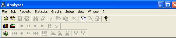
After starting the
analyzer program, you must first select the interface card from which you wish
to capture packets. This is done by
selecting the first icon on the third raw of the tool bars:
On the windows that
opens, click the “select adapter” button and select one of the network cards
shown in the list.
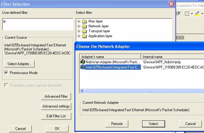
Make sure the “Promiscuous
Mode” box is checked. This will allow
the network card to capture not only packets meant for itself but all packets reaching
it on the network.
Note from the above
figure that there are many options you can use to filter-out packets you are
not interested in capturing.
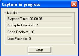
When you are ready to
start capturing packets, click the OK button.
A progress window will be displayed showing how many packets have been
captured, time elapsed, etc.
At this point try to
start an application that will trigger data transmission like using the web-browser
to access a page.
After enough packets
have been received, click the stop button to end the capture. This will automatically open the view window
that you can use to view the captured packets.
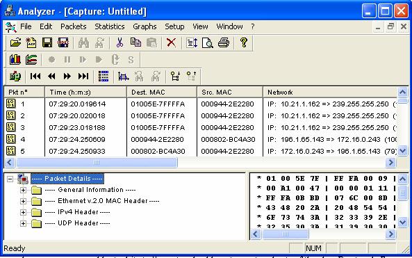
The view window is
divided into three parts. The top is the
index of the captured packets.
The bottom left shows
the details of selected packet in a tree-like structure. You can expand each tree to see more
details. The bottom-right part of the
view window shows the actual data in the packet in HEX/ASCII form.
Try and go through
the different components of some packets with different protocols and verify
the descriptions we saw earlier.
5.
Funding IP Address Information
As discussed above, when
sending data across the network, you need to know the IP addresses of the source
and destination machine.
The Windows OS family
offers many ways to determine IP configuration information, both manually and
from within a program. We look at few of these methods:
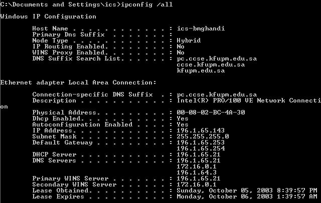
A. Using ipconfig
ipconfig
is a command line programs that comes with the OS. It can be used to display IP network
information for each active network interface on the current system. It has many options, but the most commonly
used are:
|
Z: \>ipconfig |
Displays basic IP network information about the host on which it is run |
|
Z: \>ipconfig
/all |
Displays detailed IP network information about the host on which it is
run |
|
|
|
B. Using nslookup
nslookup
is a command line programs that also comes with the OS. It can be used to query the local DNS server
about any host on the internet.
Example:
|
|
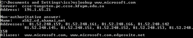
We note the following
points from the above results:
1.
The
first two lines displays info about the local DNS sever providing the query
result.
2.
Non-authoritative indicates that this information is obtained from the
cache of the local DNS server.
3.
Name
indicates the actual name of the machine – thus, www.microsoft.com is just an alias as we
can see from the last line.
4.
All
IPs associated with the machine are returned.
C. Using DNS class in C#
C# provides the DNS
class in the System.Net namespace, which provides static methods that can
be used to query the local DNS server to resolve IPs and domain names.
Some of the methods
of the DNS class are:
|
static string GetHostName() |
|
static IPHostEntry GetHostByName(string hostname) |
|
static IPHostEntry GetHostByAddress(IPAddress address) |
|
static IPHostEntry GetHostByAddress(string address) |
|
static IPHostEntry Resolve(string hostname/hostaddress) |
GetHostName returns the name of the current host.
The rest of the
methods return an instance of IPHostEnty class. This class has three properties which are
used to retrieve the information about the host, namely:
|
AddressList |
Returns an array of IPAddress objects, one for each IP Address of the
machine. |
|
Aliases |
Returns an array of string objects, one for each alias. |
|
HostName |
Returns a string object representing the name of the host. |
Example:
|
using System; using System.Net; class DNSIPInfo { public static void
{ string hostName = Dns.GetHostName(); Console.WriteLine("Local hostname:
{0}", hostName); IPHostEntry myself = Dns.GetHostByName(hostName); foreach (IPAddress address in myself.AddressList) { Console.WriteLine("IP Address: {0}", address.ToString()); } } } |
|
|
GetHostByAddress work in the same manner, except that it takes IP
address as argument.
The Resolve
can take both hostname and IP address as argument.
6.
Tasks:
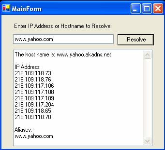
Write
a windows application that allows a user to enter a host name or ip address in
a text field – you need to use the
Resolve method.
On
clicking a button, the program
should obtain the host name, list of its IP addresses and list of its aliases and
display them in a text box one per line, as show below.
Test
your program using the following test data:
www.yahoo.com
ics-bmghandi
kfupm.edu.sa
ccse.kfupm.edu.sa
196.1.65.148