Civil Engineering Dept.
CE 201 Engineering
Statics
Dr. Rashid Allayla
Lecture 1
General Principles
(1.1-1.6)
|
|
Fundamentals:

Scalar
versus Vector:
Scalar
quantity is a quantity that has magnitude
only and is independent of direction. Examples include: Time, Speed,
Volume and Temperature. On the other hand, vector quantity has both magnitude and direction. Examples
include: Force, Velocity and Acceleration.
Graphical
representation of a vector:

The
symbol → above the letter q indicates that q is
vector. The magnitude of q is designated as by the symbol ׀q׀.
Basic
definitions:
 Length: Designated by the letter L (cm,
mm, m, km, inch, ft, mile)
Mass:
Designated by the letter M (kg, lb)
Force: Designated
by the letter F (N Newton, lbf pound force)
Particle: A particle is a mass of negligible size with no
particular geometry.
Rigid
Body: It is a combination of
large number of particles that occupy more than one point in space and located a
fixed distance from each other both before and after applying a load.
Concentrated
Force: All loads are acting on a point
on a very small body.
Newton
Newtons Laws of Motion: http://scienceworld.wolfram.com/biography/photo-credits.html
- Newton
First Law:
A particle
in a state of uniform motion or at rest tends to remain in that state unless
subjected to an external force".

Example:
A 10 N object is moving at constant speed of 10 km / hr on
a friction free surface. Which one of the horizontal forces is necessary to
maintain this state of motion?
a) 0 N b)
1 N c)
2 N ?
Answer:
It does not take any force to maintain the motion as long as
the surface is friction free. Any additional force will accelerate or
decelerate the motion depending on the force applied.
Second Law:
The
acceleration of a particle is proportional to the resultant force acting on it
and moves in the same direction of this force
f = ma
Where f is
the force, m is the mass and a is the acceleration. In this notes, instead
of placing arrows above forces, they will be written in bold letters
instead.
Third Law:
For every action there is reaction. The mutual forces of action
and reaction are equal in magnitude and opposite in direction and collinear in
orientation".
F (Action)
F (Reaction)

Online Conversion Unit: Go to http://www.onlineconversion.com/
SI Units:
SI is known as the International System of Units where
Length is in meters (m), time is in seconds (s),
and mass is in kilograms (kg) and force is in
Newton (N) (1 Newton is the force required to give 1 kilogram of mass
an acceleration of 1 m/s2).
US Customary System of Units (FPS); is the system of
units where length is in feet (ft), time is in seconds (s),
and force is in pounds (lb).
The unit mass is called a slug (1 pound is the force required to give
one slug of mass an acceleration of 1 ft/s2).
Conversion of Units:
Force; 1
lb (FPS Unit) = 4.4482 N (SI Unit)
Mass; slug (FPS Unit) = 14.5938 kg (SI
Unit)
Length; ft (FPS Unit) = 0.304 m (SI Unit)
Prefixes:
Giga = G = 109 = 1 000 000 000 Milli = m = 10-3 =
0.001
Mega = M
= 106 = 1 000 000 Micro
= μ = 10-6
= 0.000 001
Kilo = k = 103 = 1 000 Nano = η = 10-9
= 0.000 000 001
Example:
If one lb of an object has a mass of 0.4536 kg, find
the weight in Newton's.
 Solution: Mass Acceleration Force

Weight in Newton's:
(0.4536 kg) (9.807 m / s2) = 4.448 N
A force
represents an action of one body on another. A force is defined by the
following components:
a) Point of
application b) Magnitude c) Direction


Forces F1 and F2
acting on a particle may be replaced by a single (resultant) force R which will have the same effect on the particle. The
resultant force R can be found by constructing a parallelogram. So it is
evident that vector addition does not obey ordinary arithmetic addition, that
is, two forces of 9 and 3 lb magnitudes do not add up to 12 lb. On the other
hand, if the two vectors are collinear (i.e. acting on the same line),
arithmetic addition (or scalar addition) will apply.


Vector Addition Using Triangular
Construction:
Required:
Add the two vectors A and B


Method: We
can add the two vectors by connecting the tail of B
to the head of A or connecting the head of B to the tail
Vector Subtraction Using Triangular
Construction:
Vector subtraction is a special case
of vector addition. It is carried out by reversing the sign of the vector to be
subtracted and performing the same rule of vector addition
Required: Subtract vector B from A


Resolution of a Vector:
Resolution of a vector into two
vectors acting along any two given lines is carried out by constructing
parallelogram as shown in the illustration below:

Vector Addition of Number of Forces:
Vector addition of n forces is
accomplished by successive application of parallelogram
law as
described above and as shown in the following illustration:
Law of Sine and Cosine:
The magnitude of the resultant force
can be obtained using the law of cosines and the direction can be obtained
using the law of sines.
Given: force A
and Force B as shown below
Required: The
resultant force and its direction using Sine & Cosine laws.
Cosine Law: R = SQRT (A2 + B2 2 AB Cos β)
Sine Law: A/Sin γ = B / Sin α = R/ Sin β


Resolving
Resultant to Components Using Law of Sine:


Ax = - A Cos α = A Cos (180 - α)
Ay = A Sin α = A Sin
(180 α) Note that: Ax ≠ A Cos α
EXAMPLE:
Determine the magnitude and
direction of force P such that the resultant of the two forces on the pulling
tug boat (P & T) is equal to 4.00 kN.
Solution:
Using Cosine Law: P = SQRT [ 42 + (2.6)2
- 2 x 4 x 2.6 cos 20o]
Gives: P = 1.8 kN
Using Sine Law: 2.6 / Sin θ = 1.8 / Sin 20o Gives: θ = 30o
P
θ
P 2.6 N
20o
2.6 N
θ 4.0 KN
|
|
The
resultant is found using triangular law (see figure) R = 4.0 KN
EXAMPLE: (Beer & Johnston)
Two
forces A = 40N and B = 60N acting on bolt C. Determine the magnitude and the
direction of the resultant R using law of Cosine & Sine.
B = 60 N

 25o
25o
 A = 40 N

 20o
20o
Solution:
 Drawing the system using triangular rule and applying the
law of cosine: A = 40 N

 25O
25O
 R2 = A2 + B2 2 AB Cos [β)]
But: β = 180-25=155
 B=60 N R
 = (402)
+ (602) 2 (Cos 155)
β


 θ
α
= 97.7 N
Applying
the law of Sines:
A / Sin α = R / Sin 155 where
α is the angle opposite to vector A.
40
/ Sin α =
97.7 / sin 155o then α =
Sin-1 (40) Sin 155 / 97.7 = 0.173 = 10o
Then θ = (25+20) 10 =
35o
EXAMPLE: (Beer & Johnston)
Two forces are applied as
shown to a hook support. Using trigonometry and knowing that the magnitude of P is 14lb, determine (a) the required
angle α if the resultant R of the two forces applied to the
support to be horizontal, (b) the corresponding magnitude of R.


 Solution: 20 lb 30o
 Force
Triangle: R α α
 20 lb
P =14 lb


 P = 14 β
 R α 30o
P = 14 lb
Using law of sines:
20 / Sin α =
P / Sin 30 = R / Sin β
Since P = 14 lb,
then: Sin α = (20 / 14) Sin 30 =
0.71428 → α = 45.6o
The value of β: β + α + 30 = 180 → β = 104.4 then 14 /
Sin 30 = R / Sin 104.4 Gives
R = 27.1 lb
Lecture 3
Force Vectors
Addition of System of Coplanar
Forces (2.4)
|
|
The
successive application of parallelogram method to find the resultant of set of
forces is often tedious. Instead, it would be easier to find the components of
the forces along specified axis algebraically and then find the resultant.
It is often desirable to resolve a
force into two components which are perpendicular to each other as shown below.


 In
order to obtain the resultant of a set of coplanar forces, each force is
resolved into x and y components and then added algebraically to obtain the
resultant. In the figure below, F1, F2 and F3
are a set of coplanar forces. In Cartesian vector notation, the forces are
written as


 F1 F2
F1 F2
 F3y F3x
F3
F1
= - F1x + F1y , F2
= F2x + F2y ,
F3 = F3x - F3y
The resultant is: FR = F1 + F2 + F3
Angle resultant makes with + x axis
FR
= (-F1x + F2x + F3x) i + (F1y
+ F2y F3y) j
& ІFR І
= SQRT ( FRx2 + FRy2 ) θ = Tan-1 (ІFRy І
/ ІFRx І )
)
Unit
Vector:
A unit vector is a vector directed along the positive x and y axis having
dimensionless magnitude of unity. Any vector can be expressed in terms of the
unit vector as, F = Fx i
+ Fy j
Where i and j
are the unit vectors in x and y direction and Fx and Fy
are the scalar magnitudes of F in x and y direction. The two magnitudes can
be either positive or negative depending on the sense of Fx and Fy.
If θ is
measured counterclockwise from the positive x axis, the magnitude of the force
is measured as
Fx = F Cos θ and
Fy = F Sin θ
EXAMPLE: (Hibbeler)
Determine the x and y
components of F1 and F2 acting on the boom and express
each force as a Cartesian vector.
1) Scalar Notation:


F1x
= -200 Sin 30 = -100 N
F1y
= 200 Cos
30 = 173 N
F2x
/ 260 = 12/13 Gives: F2x =
240 N
F2y
/ 260 = 5/13 Gives: F2y = 100 N
2)
Cartesian Notation:
Having
determined the magnitudes of forces and their directions, then:
F1
= --100 i + 173 j
F2
= 240 i 100 j
EXAMPLE: (Beer & Johnston)
Four
forces act on bolt A, determine the resultant of the forces on the bolt.


Force Magnitude N X-Component N Y-Component
F1 150 +129.9 + 75.0
F2 80 -27.4 + 75.2
F3 110 0.0 - 110.0
F4 100 +96.6 - 25.9
Rx
= +199.9 Ry =
+14.3
|
|


 F2 F1
F2 F1
 F4
F4
 F3 F1 Cos
30 i
F4 Cos 15 i
-F2 Cos 20 i

θ = Tan-1 ( 14.3/199.9)
= 4.1o
EXAMPLE:
Determine
magnitude and direction cosine of resultant (R) of the following force vectors:
F1 = 5i + 15 j + 30 k (N)
F2 = 25i +
30 j - 40 k (N)
F3 = - 25j
-
50 k (N)
Solution:
R = ∑ Fi = F1
+ F2 + F3
R
= 30 i + 20 j - 60 k R = SQRT
[(30)2 + (20)2 + (60)2] = 70 N
Cos α = Rx / │R │ = 30 / 70 = 0.42857 α = 64.6o
Cos β = Ry /
│R │ = 20 / 70 = 0. 28571 β =
73.4o
Cos γ = Rz / │R │ = -60 / 70
= -0.8571 γ =
149.0o
Check
the result Cos2 α + Cos2
β + Cos2 α = 1
(0.42857)2 + (0.28571)2 + (0.8571)2 = 1 OK
Lecture 4
Force Vectors
Cartesian Vectors (2.5, 2.6)
|
|
Cartesian Vectors
Cartesian
vector is a set of unit vectors i, j and k that defines
the direction of a given vector. It locates a point in space relative to
a second point. Unit vector in the direction of a given vector (such as the one
shown in the figure) is obtained by dividing the position vector rAB
by the magnitude of rAB:
z
B (xB, yB, zB)
A
Y rAB = (XB
XA) i + (YB YA) j + (ZB ZA)
k
│rAB│
= SQRT [ (XB XA)2 + (YB
YA)2 + (ZB ZA)2 ]
Unit Vector uAB =
rAB / │rAB│ = (XB XA)
i + (YB YA) j + (ZB ZA) k /
SQRT
[ (XB XA)2 + (YB YA)2
+ (ZA ZB)2 ]
zA xA
yA
x
|
|
 C
C
Unit vector
is useful to express a force in a vector form. When a unit vector acting in the
same direction of the force is multiplied by the magnitude of the force, a
vector representation of the force is accomplished.
F = │F│uAB and, therefore, ux = Fx
/ │F│ uy = Fx / │F│ ux = Fz / │F│


UF
= (Fx / │F│) i + (Fy /
│F│) j + (Fz / │F│) k Then:
U = Cos α i + Cos β j + Cos γ k
Note that the sum of squares of
direction cosines is unity because │uF│
= 1
Cos α2 i + Cos2
β j + Cos2
γ k = 1
EXAMPLE: (From umr)
Determine
the distance between point A and B located as shown using a position vector.

4 m
Solution:
The
position vector in the direction AB is
rAB
= (XB XA ) i + ((YB YA )
j + (ZB ZA ) k
= (4 (-2)) i +(12 (-6)) j
+ (-2 3 ) k = 6 i + 18 j 5 k m
The
distance from A to B is │r │ = SQRT[( 62 +182
+ 52 )]= 19.62 m
EXAMPLE: (From Hibbeler)
Determine the magnitude and the coordinate direction
angle of the resultant force acting on the ring.


The
resultant force FR = (50+0) i + (-100+40) j + (100+80)
k = 50 i 40 j + 180 k
The
magnitude = SQRT [ (50)2 + (-40)2 + (180)2 ] =
191.0 lb
UFR
= (50 / 191.0 i (40 / 191.0) i + ( 180 / ( 191.0) k =
0.2617 i 0.2094 j + 0.9422 k
Then Cos
α = 0.2617 α = 74.8o and: Cos β = -
0.2094 β = 102o
and: Cos γ = 0.9422 γ= 19.6o
|
|
Lecture 5
Force Vectors
Position Vector, Force alona Line
(2.7, 2.8)
|
|
We have shown that the unit
vector along a line AB is:
 Called position vector r
u = (XB XA ) i +
((YB YA ) j + (ZB ZA ) k
/ SQRT{(XB XA )2
+ ((YB YA )2 + (ZB ZA
)2} or: u = r / │r│

If we have a
force F with magnitude of │F│acting along the line AB, then the
vector F is defined as:
F = u │F│
Where: u is the unit
vector acting along the line AB as defined above.


EXAMPLE: (From umr)
Write
a unit vector in the direction from B to A
Solution:
The
unit vector from B toward A UBA = rBA / │ rBA
│ and the position vector is:
rBA
= (XA XB) i + (YA YB) j + (ZA
ZB) k
= (-6 3) i + (8 (-4)) j + (5- (-2))
k
= -9 i + 12 j + 7 k m
The
magnitude of the unit vector uBA is: UBA = rBA /
│ rBA │
Where,
rBA = SQRT [(9)2 + (12)2 + (7)2] = 16.553 Then:
UBA
= (-9 i + 12 j +
7 k) / 16.553 = -0.5437 i + 0.7249 j + 0.4229 k
EXAMPLE : (Beer & Johnston)
A
towe guy wire is anchored by means of bolt at A. The reaction in the wire is
2500 N. Determine a) the components Fx, Fy and Fz,
b) The angles α, β and γ


The
distance from A to B = SQRT [ (40)2 + (80)2 + (30)2]
= 94.3 m Then:
Position
vector: rAB = - 40 i + 80 j + 30 k ,
The unit vector uAB = - (0.4242) i + (0.8484) j + (0.3181) k
The
vector Along AB = [ (2500) uAB ] =
- (1060.5 N) i + (2121 N) j +
(795.33 N) k
Direction
of force: α = Cos-1 [-1060 / 2500] = 115.1o, β = Cos-1 [2120 / 2500] = 32.0o, γ
= Cos-1 [795 / 2500] = 71.5o
Example: (Hibbeler)
A
roof is supported by cables as shown. If the cables exert forces FAB
= 100 N and FAC 120 N on the wall hook at A as shown. Determine the
resultant force at A and its magnitude.


The
position vector AB: rAB = (4 m 0) i + (0 0) j + (0 4 m) k = 4 i 4 k
׀rAB׀ = SQRT [ (4)2
+ (-4)2] = 5.66
m
Then: FAB
= (100 N) [ rAB / ׀rAB׀
] = (100 N) [ (4 / 5.66) i (4 / 5.66) k ]
FAB
= [70.7 i 70.7 k] N
The
position vector AC rAB = (4 m 0) i + (2 m 0) j + (0 4 m) k = 4 i + 2j 4 k
׀rAC׀ = SQRT [ (4)2
+ (2)2 + (-4)2] = 6 m
Then: FAC
= (120 N) [ rAC / ׀rAC׀
] = (120 N) [ (4 / 6) i + (2 / 6) (4 / 6) k ]
FAC
= [80 i + 40 j 80 k] N
The
resultant force is:
FR
= FAB + FAC = [70.7 i 70.7 k] + [80 i + 40 j 80 k]
= [150.7 i + 40 j 150.7 k] N
׀FR׀
= SQRT [ (150.7)2 + (40)2 + (-150.7)2 ] = 217 N
Lecture 6
Force Vectors
Dot Product (2.9)
|
|
Dot product
of two vectors P and Q (otherwise known as scalar product) is defined as the
product of the scalar magnitudes of the two vectors and the cosine of the angle
formed by the vectors. Dot product is useful for:
a) Determining
the angle between two vectors, and,
b) Determining
the projection of a vector along a specified line.
Let: P = Px i + Py
j + Pz k
and: Q
= Qx i + Qy j + Qz k
Then: P.Q = │P││Q│
cos θ Ξ Px Qx + PyQy + Pz
Qz
Rules:
1)
Dot product follows commutative law: Q . P = P.Q
2)
Dot Product follows distributive law: P. (Q1 + Q2) = P. Q1 + P. Q2
3) Multiplication by a scalar: a (P.Q) =
(a P) . (Q) = (P) . (a Q) = (P.Q) a


 uP
= P /│P│
P.Q =
│P││Q│ cos θ or:
cos θ = [P.Q /
│P││Q│] or: θ
Ξ cos-1 (uP . uQ)
Since │Pa-a│
= │P│cos θ
Then: │Pa-a│
= P. ua-a and Pa-a = [ P . ua-a ]
uaa
 Usefulness of Dot Product:
Vector form of
projection of F into x axis
 -
Angle between two intersecting vectors can be determined:

 θ =
cos-1 [P.Q / │P││Q│]
- The
component of a vector parallel and perpendicular to a line can be determined if
the unit vector along this line is known:
F ║ = F cos θ = F. u
Since F
= F ║+ F ┴ Then:
F ┴ = F - F ║
Projecting a Force along a Line:
Given: A force FAB
= A i + B j + C k along line
AB
Required:
The projection
of this force along line AC
Method
of solution:
1) Find the unit vector along
the line AC
UAC = [(xC xA) i + (yC
yA) j + (zC zA)] / SQRT [[(xCxA)2+[(yC
yA)2+ [(zC zA)2]
2) Use the dot product to find
the projection of the force along AC:
׀FAC׀ = UAC
. FAB

׀FAC׀ = { [(xC
xA) i + (yC yA) j + (zC zA)]
/ SQRT [[(xCxA)2+[(yC yA)2+
[(zC zA)2]}
. { A i + B j + C k }

This is scalar value which is the projection of force F into line AC
The Cartesian vector of the projection of F into AC is:
FAC = UAC ׀FAC׀


EXAMPLE 1: (from umr)
The force F = 50i + 75 j + 100 k
acts on a pole AB as shown. Determine the projected component of F along AB and
component of the force perpendicular to AB.


The
unit vector along AB = rAB /│ r │ = {(4-3) i +
[4-(-2)] j + (6-0) k} / SQRT[12 + 62 + 62
]
Then:
uAB = (0.117 i + 0.702 j + 0.702 k) (This is the
unit vector along AB)
FAB
(the projection of F on AB) = F . uAB = ( 50i + 75 j +
100 k) . (0.117 i + 0.702 j + 0.702 k)
= 23.41 lb
The
Cartesian vector from the parallel component is FAB . uAB
= 23.41 (0.117 i + 0.702 j +
0.702 k)
F║ = 2.74 i + 16.44 j + 16.44 k lb
The
component of the force perpendicular to AB is = F FAB = (50i
+ 75 j +100 k) (2.74 i + 16.44 j + 16.44 k) lb
F┴
= 47.3 I
91.4 j + 85.6 k lb
EXAMPLE 2:
Find
the a) angle between cable BD and the boom AB and b) the projection on AB of
cable BD at point B.


Unit
vector in AB direction = ( 6 i + 4.5 j ) / SQRT ( 62 +
4.52 ) = 0.8 I + 0.6 j

The angle between BD and AB
is = cos-1 [ uAB
. uBD ] = cos-1 [(0.8i +0.6j) . (-0.67i
+0.33j -0.67 k) ]
= cos-1 [-
0.536 + 0.19] = 110.24o
Force BD = (180) (uBD)
= (180) (-0.67i +0.33j -0.67 k) = - 120.6
i + 59.4 j + 120.6 k
The projection of BD on AB =
uAB . FBD = (-0.8i +0.6j ).(- 120.6 I + 59.4 j + 120.6 k)
= - 96.48 + 35.6
= 60.88
Lecture 7
Equilibrium of Particle
Free Body Diagram (3.1, 3.2)
|
|
Conditions for Equilibrium of a Particle:
A particle is said to be at
equilibrium if the resultant of all forces acting on it is zero. Another case
of equilibrium is illustrated in the figure below. If the four forces acting on
a particle at point O are at equilibrium, then starting from point O with F1
and arranging the forces in tip to tail fashion, the tip of F4 will
coincide with the tail of force F1 and the resultant of the four
forces will be zero. The graphical representation is expressed mathematically
as:
∑ F = 0
Free-Body
Diagram:
What? - It
is a drawing that shows all external forces acting on the particle.
Why? - It helps
you write the equations of equilibrium used to solve for the unknowns (usually forces or angles) (Hibbeler)
Therefore:
- Free
body diagram is a method of isolating all external forces acting on a body from its surroundings.
Procedure for Drawing Free Body Diagram (FBD):
1) Isolate the particle from its
surroundings.
2) Sketch all forces that act on the
particle while observing Newtons third law which notes the existence of equal and
opposite reaction to every action.
3)
Known
forces are labeled with their magnitudes
and directions. Assign letters to the unknown forces with assumed
directions. The bodys weight must be included if applicable.
EXAMPLE:
Draw the free body
diagram of the two structures shown
Springs:
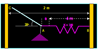
The magnitude of
the force exerted on the linear elastic spring is:
F = Ks
Where K is the stiffness of the spring (measured in N/m), s is the deformation (which is a measure of the
difference between the deformed length L and the undeformed length L0).
Note that if s is negative, F must push on the spring and if s is positive, F
must pull on the spring to bring it to the desired length. K is also defined as the force
required to deform the spring a unit distance.
EXAMPLE:
A spring has undeformed length of 0.4 meters and
stiffness k = 500 N/m. What is the force needed to stretch the spring to a length
of 0.6 m? and what force is required to compress the spring to a length = 0.2
m?
SOLUTION:
F = K s
F = (500 N/m) (0.6 m 0.4 m) = 100 N (s is positive, force is pulling spring)
F = (500 N/m) (0.2 m 0.4 m) = -100 N (s is negative, force is pushing spring)
Cables and Pulleys:
When a cable is passing over a
frictionless pulley, the force along the cable is always in tension and
constant in magnitude. This is necessary condition to keep the cable in
equilibrium.
EXAMPLE:
The springs
have stiffness of 500 N/m each and length of 3 m each. Determine the horizontal
force F applied to the cord so that the displacement of the pulley from the
wall is d = 1.5 m.
SOLUTION:
 T
T
 AC = 3.3541 m
F 2T
Cos θ


 Σ Fx = 0
If the tension at each spring is T
Then: Tx =
(1.5/3.3541) T
Tx
 Then, 2(1.5 / 3.3541) (T) F = 0 since: s = 3.3541-3=0.3541 m T
T = K S = (500)(
3.3541 - 3) =
177.05 N Then: F = 158 N
Lecture 8
Equilibrium of Particle
Coplanar Force System (3.3)
|
|
Procedure for Solution of Problems in
Equilibrium:
- Establish x-y Coordinate system. & Draw free
body diagram.
- Label all known forces
and unknown forces and assume the
direction of unknown forces.
- Apply the equations of equilibrium ∑ Fx
= 0 and ∑ Fy = 0.
- Compare the number of
unknowns on the free body diagram with the number of independent equations
of equilibrium available.
- If there are more unknowns to be evaluated than
the number of equations, draw a free body diagram of another body and
repeat the steps described above.
EXAMPLE : (From Higdon &
Stiles)
A 500 N
shaft A and 300 N shaft B are supported as shown. Neglecting friction at all
contact points find the reactions at points R and S at shaft A.


The
first FBD ( Shaft A ) has three unknowns Q, R and S and only two independent
equations of equilibrium. The next step is to draw FBD of shaft B. The force on
shaft B exerted by shaft A is Q directed to the upper right. Writing the
equation:
∑
Fy = 0 then: Q sin 40o 300 = 0 then Q = 467 N
on B
From the FBD of shaft A:
∑Fy
= 0 then: S 500 Q sin 40o = 0 then S
= 800 N directed upward.
∑Fx
= 0 then: R Q cos 40o = 0 then: R = 467 cos 40o = 358 N directed to the right
EXAMPLE:
(From Hibbeler)
Determine the required length of cord AC so that the 8
kg lamp is suspended in the position shown. The undeformed length of the spring
is LAB = 0.4 m and its stiffness is 300 N/m
Y
TAC
300
TAB
78.5
78.5 N
|
|




Weight
of lamp W = 8 (9.81) = 78.5 N
∑Fx
= 0 TAB TAC
cos 30o = 0
∑Fy = 0
TAC sin 30o 78.5 = 0
Then:
TAC = 157.0 N and TAB = 136.0 N which is the stretch of spring AB
TAB = K s or:
136.0 = 300 s Then s = 0.453 m (this is the amount of stretch
on the spring)
The
stretch length is LAB = LAB + SAB = 0.4 + 0.453 = 0.853 m
The
horizontal distance CB requires that 2
= LAC cos 30o + 0.853
Then LAC = 1.32.m
EXAMPLE: (from umr)
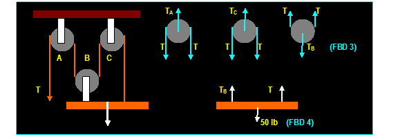
The pulley system is used to rise a 50 lb weight.
Determine the tension T necessary to hold the weight in equilibrium.


 ∑
Fy = 0 Then: from FBD (3): T + T TB = 0
Or: TB = 2 T Since: ∑ Fy = 0 Then from the FBD (4) TB + T 50 = 0 or: T = 50 / 3 = 16.67
lb
Example:
Calculate
the tension T in the cable which supports the 1000 lb load with the system of
pulley shown. Ignore the weight of the pulley. Find F at Pulley C.


Solution:
Start
with the free body diagram (pulley A) because it has the only known force:
∑ Fy
= 0
Then: T1 + T2
= 1000
Since
the cord around pulley A is continuous,
T1 = T2
Then: T1 = T2
= 500 lb ↑
Since
the cord around pulley B is
continuous, T3 = T4
= T2 / 2 = 250 lb↑
Again,
since the cord around pulley C is continues T3 = T Then: T = T3 = 250 lb ↑
Evaluation of
reaction forces at pulley C:
∑ Fx = 0 250
cos 30o Fx = 0
Then: Fx = 217 lb ←
∑ Fy
= 0
- Fy + 250 sin 30o -250 = 0 Then Fy = - 125 lb ↓ or: +125 lb ↑
F
= SQRT [ (217)2 + (125)2 ] = 250 l
Example: (Hebbeler)
The
sack at A weighs 20 lb, determine the weight of the sack at B and the force in
each cord needed to hold the system in the equilibrium position shown.

There
are three forces acting on E: TEG, TEC and 20 lb and on
C: TCE, TCD and WB
From
FBD No. 1
∑
FX = 0 Then: TEG
sin 30O TEC cos 45O = 0
∑
Fy = 0 Then: TEG cos 30O TEC
sin 45O 20 lb = 0 Then: TEC
= 38.6 lb and TEG
= 54.6 lb
From
FBD No. 3: TEC = TCE = 38.6 lb
From
FBD No. 2
∑
FX = 0 Then: 38.6 cos 45O
(4/5) TCD = 0
∑
Fy = 0 Then: (3/5) TCD + 38.6
sin 45O WB = 0
Then: TCD = 34.2 lb and: WB = 47.8 lb
Lecture 9
Equilibrium of Particle
Three Dimensional Force Systems
(3.4)
|
|
The
requirement for equilibrium of a particle is:
∑F
= 0 or: ∑Fx + ∑Fy
+ ∑Fz = 0 The method of solution is summarized as
follows:
Draw
Free body diagram and:
- Establish appropriate x,y and z axis.
- Label all
known and unknown forces and assume the direction of unknown forces.
- Apply the equations of
equilibrium ∑Fx = 0, ∑Fy = 0, ∑Fz
= 0.
- Reverse the directions of
unknown forces if solution yields negative result.
Example: (From
Hibbeler)
Determine
the magnitudes of F1, F2 and F3 for
equilibrium of the particle.


∑ Fz
= 0 F1 sin 30O 2.8 = 0 Then:
F1 = 5.6 KN
∑ Fy = 0 - F2
(24/25) + (8.5) cos 15 = 0 Gives: F2 = 8.55 k
F3 5.6 cos 30O 8.55 (7/25) 8.5 sin 15O
= 0 Then:
F3 = 9.44 k
EXAMPLE: (From
Hibbeler)
The 100 kg crate is
supported by three cords, one of which is connected to a spring. Determine the
tensions in AC and AD and the stretch of the spring


Note: FC is directed in - x, - y, +z zone, FD is directed in
x, +y, +z zone and FB is directed in +x
zone, then:
FB = FB i
FC = FC cos 120 i + FC cos 135 j + FC cos 60 k
= -0.5 FC
i
- 0.707 FC j + 0.5 FC k
FD = FD ( -1 i + 2j +
2k) / SQRT (-12 +22 + 22) = -0.333 FD i + 0.667 FD j + 0.667 FD k
W = - 981 k
Σ F = 0 Then:
Σ F = 0, then: FB i - 0.5 FC i
0.707 FC j + 0.5 FD i + 0.667 FD j + 0.667 FD k 981 k = 0
Setting Σ Fx = 0 , Σ Fy = 0 , Σ Fz = 0 We
have three unknowns and three equations, then:
FC = 813 N
FD = 862 N
FB = 693.7 N
The stretch of the spring is
FB = k s
693.7 = 1500 s Then s = 0.462
m
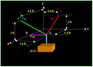
EXAMPLE: (From
Hibbeler)
A 200 lb box is
supported by cables DA, DB and DC find the forces in these cables


Σ Fx =
0 Then:
(4.51.5) i / SQRT[( 4.5-1.5)2+(-1.5)2+(3)2
] FDA + (-1.5) i / SQRT[
(-1.5)2 + (2.5-1.5)2 +(3)2 ] FDC
= 3 / 4.5 FDA 1.5
/ 3.5 FDC = 0.667 FDA - 0.429 FDC = 0
Σ Fy=0 Then:
(1.5) j / SQRT [( 4.5-1.5)2+(-1.5)2+(3)2
] FDA + (2.5-1.5) j / SQRT [(1.5)2+(3)2+(2.5-1.5)2]
FDC
+ (-1.5) j / SQRT[( 1.5 )2 + 0 + 0) ] FDB
= -1.5/ 4.5 FDA + 1 /
3.5 FDC - FDB = - 0.33 FDA + 0.286 FDC - FDB = 0
Σ Fz =
0 then:
(3) k /SQRT[(4.5-1.5)2+(1.5)2+(3)2]
FDA+(3)
k /SQRT[(1.5)2+(3)2+(2.5-1.5)2]
FDC W k
= 3 / 4.5 FDA + 3 /
3.5 FDC - 200 = 0.667 FDA + 0.857 FDC 200 = 0
The above are three
equations and three unknowns FDA, FDB and FDC.
Solving yields:
FDA = 100 lb FDB
= 11.1 lb
, and: FDC = 155.6 lb
|
|
Lecture 10
Force System Resultant
Moment of a Force-Scalar
Formulation (4.1)
|
|
A moment of a force around a
point (say O) is a measure of the tendency of the force to rotate the body
around the point. The magnitude of the moment is found by multiplying
the magnitude of the force with the shortest distance from the force to that
point. The sense the moment vector is determined by the right-hand rule defined
earlier.
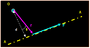
If F is a
force along A-A line, the magnitude of the moment of the force around point O
is:
Mo
= │F│ d = │F││r│sin θ Where θ is the angle between the
two vectors
Here: d is the moment arm which is the
perpendicular distance from O to the line A-A.


F is
parallel to x-y axis F is
parallel to z-y axis F
passes through 0
EXAMPLE
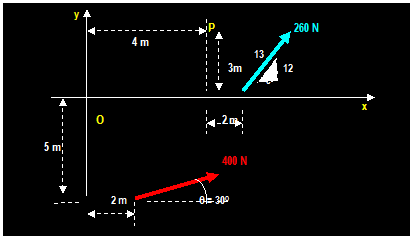
(From Hibbeler)
Determine
the magnitude and the directional sense of the resultant moment of the force
about point P.
Solution:
 +
+
MP = (260) (5/13) [3] +(260)
(12/13) [2] (400) (sin 30o) [4-2] + (400) (cos 30o)
[3+5]
= 300 + 480 400 + 2771.28= 3151 N
EXAMPLE:
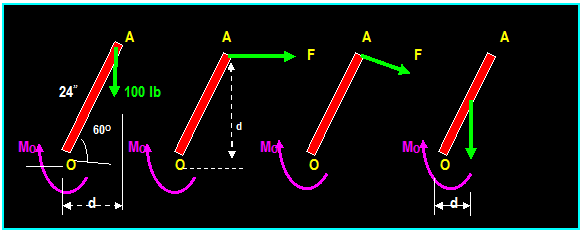
A 100 lb vertical force applied to the end of a lever
attached to a shaft. Determine 1) The moment about O; b) The magnitude of
horizontal force applied at A which creates the same moment about O; c) The
smallest force applied at A which creates the same moment about O; d) How far
from the shaft a 240 lb vertical force must act to create the same MO

a)
d = 24 cos 60 = 12 in
MO = (100 lb) (12 in) = 1200 lb-in Perpendicular to
the paper and pointed into the paper.
b)
d = (24 in) sin 60 = 20.8 in Then: MO = 1200 = (20.8) F or: F = 57.8 lb
c)
The smallest value of F occurs when d is maximum which is 24 inches, then
1200 = F (24) Then:
F = 50 lb
d)
1200 = (240) d Then: d = 5 in
EXAMPLE:
(From Hibbeler)
Determine
the resultant moment of the four forces acting on the rod shown below.


Assuming
that positive moment acts on the +k direction (counterclockwise), then:

+M R0
= Σ F d
M R0 = -
50 N (2 m) + 60 N (0) + 20 N (3 Sin 30o m) 40 N (4 m + 3 Cos 30o m)
= - 334 N.m

= 334 N.m
Example:
(From Hibbeler)
The
70 N force acts on the end of the pipe at B. Determine the angle θ (0o
< θ > 180) of the force that will produce maximum
moment about point A. What is the magnitude of the moment? (a = 0.9 m, b = 0.3
m and c = 0.7 m)
MA
= F sin (θ)
c + F cos (θ) a
dMA/d θ = 0 = F cos (θ) c - F sin (θ) a
θmax = atan (c/a) Gives:
θ = 37.9o
Mmax = (70 N) sin (37.9o)
(0.7 m) + (70 N) cos (37.9o) (0.9 m)
Mmax = 79.812 N.m
|
|
Lecture 11
Force System Resultant
Cross Product (4.2)
|
|
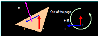
Direction
of Moment:
The direction
of moment is determined using the righthand rule. Starting from the position r
and curling fingers into the force F, the direction of the moment is parallel
to the direction of the thumb (i.e.: perpendicular to the plane formed by the vectors r and F). We
can also use the principle of screw where the direction of the movement of the
screw as it is driven, is the same as the direction of the moment when the
turning action of the screw is directed from r to F.
Direction of moment
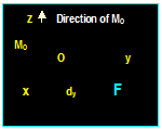
z
Direction of fingers from r to F
x y
r
Position Vector r F
|
|




![in00978_[1]](CE_201_files/image238.gif)
![j0311556[1]](CE_201_files/image240.gif)

Cross Product:
Cross product
of vectors Q and P is
a vector V = Q X P directed perpendicular to the plane containing the
two vectors. The magnitude of the resulting vector is the product of the
magnitudes of the two vectors multiplied by the sine of the angle formed by Q and P. The
direction of the resultant vector is determined using the right-hand rule. This
suggests that the commutative rule does not apply in cross products as:
V = P X Q
Q P  V = Q X P V = Q X P
Q
|
|
 P X Q ≠ Q X P

 However, distributive law can be
applied as:
A X (B + C) = (A X B) +
(A X C)
The cross
product of two vectors P X Q in Cartesian coordinate system is:
P X Q = (Px i + Py j + Pz k ) X ( Qx i + Qy j + Qz k)
= Px Qx (i X i) + Px Qy (i X j) + Px Qz (i X k) + Py Qx (j X i) + Py Qy (j X j) + Py Qz (j X k)
+ Pz Qx (k X i) + Pz Qy (k X j) + Pz Qz (k X k)
Noting that: (i X i) = (j X j) = (k X k) = 0 and: (i X j) = (j X k) =
(k X i) = 1
(j
X i) = (k X j) = (i X k) = -1
i
j k
P X Q = (Py Qz- Pz Qy) i (Px Qz Pz Qx) j + (Px Qy Py Qx) ki = │ Px Py
Pz │
Where the symbol │
│
is known as the determinant Qx Qy Qz
EXAMPLE:
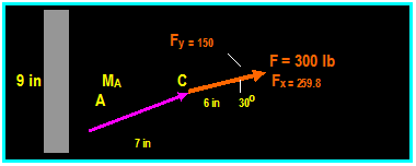
A
300 lb force acts on bracket as shown. Find the moment MA about
point A


The
moment is the vector MA = r X F where r is the vector pointing from
A to C
Mx
= 300 cos 30Oi(6) =1558.8
in-lb My =300 sin 30O (7) = 1050
Then
MA = 1558-1050 = 508.8 in-lb Pointing
into paper
i j
k
MA
= r X F = | 7
6 0 | = (7x150 6x259.8) k
= 508.8 k (-) Pointing into the paper
259.8 150 0
Example:
Determine the direction θ for 0O ≤ θ ≥ 180O
of the force F so that F produces a) the maximum moment about point A, b)
the minimum moment about point A.


The
maximum moment produced when F ┴ BA
MA = 400 [√
( 32 + 22) ] = 1442 N-m
Since: Ф = tan-1 (2/3) = 33.69O
Then θ = 90O 33.69= 56.3O
b) MA = 0 Then: θ = 180O 33.69O = 146O
|
|
Lecture 12,13
Force System Resultant
Moment of a Force-Vector
Formulation (4.3,4.4)
|
|
Principle
of Transmissibility:

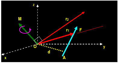
The force
applied at point A (shown above) produces a moment M about point O at the
direction shown. The moment produced is:
M = F x r1
= F x r2 = ׀ F ׀
׀ r ׀
sin θ = F d
It is evident that the moment produced is the
same as long as the position vector r is taken from point O to any point along
the line of action of force F (This is called principle of transmissibility)
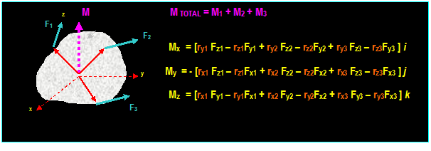
Resultant
Moment of a Set of Forces:

The total moment above is:
(MR)O = ∑(r X F)
The moment M of F about an axis
through O is a vector normal to a plane
formed by F and r and is calculated as:
i
j k
M =
│ rx ry
rz │= [ry Fz rzFy]
i - [rx Fz rzFx] j +
[rx Fy ryFx] k Ξ r X
F
Fx Fy Fz
│M
│ = │r│ │F│ sin θ = │F│d
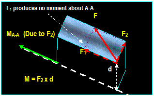
The moment
about point O in any given space can be interpreted as the moment about an axis
passing through point O and perpendicular to a plane containing point O and
force F. The Cartesian representation of
moment vector is:
i
j k
MO
= r X F = │ rx ry rz │= [ry
Fz rzFy] i - [rx Fz
rz(-Fx)] j + [rx Fy ry(-Fx)]
k
 -Fx Fy Fz
Where: r is
the position vector connecting point O to any point on the line of action of F.
 F
F
z

 (MO)z
(MO)z
 r
r





 rz
y
rz
y
 rx
(MO)y
 ry
ry
x (MO)x
 The
i component
of the moment is the result of three moments: one due to Fx
about the x axis (but
producing no moment since Fx is parallel to x-axis), the second is due to Fz about
the x-axis (Ξ +ry
Fz acts in the positive x-axis), the third
is due to Fy about the x-axis (Ξ - rzFy acts in the negative x-axis).
Similarly:
The j component of the
moment is the result of three moments: one due to Fy about
the y axis (but producing no moment since Fy is
parallel to y-axis), the second is due to Fz about
the y-axis (Ξ - rx Fz acts in the negative y-axis), the third
is due to Fx about the y-axis (Ξ - rzFx acts in the negative y-axis). Also: The k component of the
moment is the result of three moments: one due to Fz about
the z axis (but producing no moment since Fz is parallel to z-axis), the second
is due to Fy about the z-axis (Ξ + rx
Fy acts in the positive z-axis), the third
is due to Fx about the z-axis (Ξ + ryFx acts in the positive y-axis).
Example:
A
force P and Q of magnitude 50 N and 100 N act in the directions shown. Determine
the moment of P about point F.
2 i - (9-5) j + 6 k
P
= 50 N [ ---------------------------] = 50 (0.267 i 0.535 j + 0.802 k) = 13.35 i
26.75 j + 40.10 k
SQRT( 4+16+36)
Q
= - 100 N j
rFB
= (0-10) i +(9-0) j + (0-4) k = - 10 i + 9
j 4 k
rFD
= (0-10) i +(0-0) j +(0-4) k = - 10 i 4
k
i j k i j k
MF
= rFB x P + rFD x Q
= | -10 +9
- 4
| + | -10
0 - 4 |
13.35 -26.75
40.10 0
-100 0
= [9x40.1
(-4x(-26.75)]i[-10x40.1(-4x13.5) ] j+[-10x(-26.75)-9x13.35]
+[-(-4)x(-100)] i
+0 j +[-10x(-100)] k
= (360.9 - 107) i +(400.1 - 54) j + (267.5 120.15) k - 400 i + 1000 k
= 253.9 i +
346.1 j + 147.35 k - 400 i + 1000 k
= - 146.1 i+346.1 j+1147.4 k
Alternative
way: Using rFB as an arm for both forces:
i j k i j k
MF
= rFB x P + rFD x Q
= | -10
+9 -4 | + |
-10 +9 -4
|
13.35 -26.75 40.10 0
-100 0
= (360.9 - 107) i +(400.1
- 54) j + (267.5 120.15) k - 400 i + 1000 k
= - 146.1 i+346.1 j+1147.4 k
|
|
Lecture 14
Force System Resultant
Moment of a Force about Specified
Axes (4.5)
|
|
Approaches Used to Obtain Moments about Specified Axis:
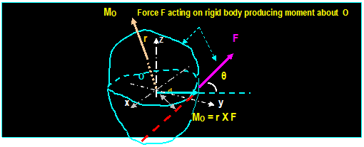
Consider a force F acting on a rigid body
containing point O as shown. The moment of this
force about a given axis, say a-a, passing
through point O, can be found by applying the cross product between the
position vector OA with the force F producing moment MO
perpendicular to the plane formed by F
and OA and projecting the resulting moment into axis a-a.
1)
Scalar
Approach:
Alternatively, the moment about the axis can be found by resolving F into its three components, finding the individual
moments about O by multiplying the force
components with shortest distance between the force and the point in question.
Finally, the moment about the axis is computed by projecting the moments into
the axis in question and adding them algebraically.
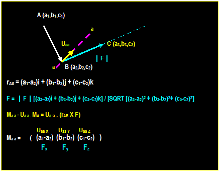
2) Triple Scalar
Product:
It was pointed out earlier that the projection of any vector into a
specified axis is found by performing
the dot product of the vector with a unit vector in the direction of the axis.
In the above, if MO is the
resulting moment of F about point O, the moment of F
about the axis a-a is obtained by performing
the dot product of the moment of F about point O with u a-a where
u a-a is the unit vector
in the direction of the line a-a. The magnitude of Ma-a
is:
Ma-a = MO cos θ, which, in
general, can be written as:
Maa = ua-a
. MO = ua-a . (r x F).
Writing the
equation in matrix form:
(ua-a
)x (ua-a )y
(ua-a )z
Ma-a
= u a-a . (r x F) Ξ │ rx ry rz │ This quantity known as the triple scalar product
Fx Fy Fz
The vector form of the moment
about a-a is:
Maa = [ua-a
. (r x F)] uaa
If there is more than one force, the moment about a-a:
Ma-a = ∑
[ua-a . (r x F)] = ua-a . ∑(r
x F)]
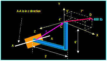
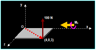
Example:
What is the moment of the
100 N force about the x axis


1) Vector Method:
Taking r from any point in
x - axis to any point in vector force F:
r
= 4i + 3k
F
= (100) [ j ] = 100 j
i j
k
MO = ׀ 4
0 3 ׀ = - 300 i + 400 k
0 100
0
׀ Mx ׀ = ux . MO = (i) . (-
300 i + 400 k) = - 300
Mx = ׀ Mx ׀ux
= - 300 i
2) Triple Scalar
Product Method:
The unit vector along x-
axis is i then:
׀ Mx ׀ = [ i . (r x
F)]
1 0
0
׀ Mx ׀ = ׀
4 0 3 ׀ = - 300
0 100
0
Mx = ׀ Mx ׀ux
= - 300 i
Example:
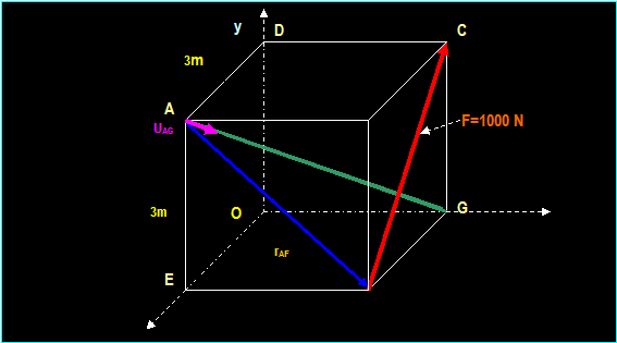
A cube of sides 3 meters is acted upon a force F =
1000 N. Determine the moment about the diagonal AG.
Length
of CF = √ [(3)2 + (3)2] = 4.24
The
force F in rectangular components: (1000 / 4.24) [ 3j 3k] = 707.1 j 707.1 k
And: rAF
= 3i -3j
i j k
The
moment about A is: MA = rAF
x F = │ 3 -3 0 │ = 2121 i + 2121 j + 2121 k
0 +707.1
-707.1
Moment
about AG = uAG . MA
Unit
vector along AG uAG = (1/SQRT ( 32 + 32 + 32
)[ 3i - 3j 3k] = 0.577 i - 0.577 j
0.577k
MAG
= uAG . MA = [0.577 i
0.577 j 0.577 k ] . [ 2121 i + 2121 j +
2121 k] =
1223.8 - 1223.8 1223.8 m-N
 = 1223.8 m-N
Alternative
method:
The
moment about AG is:
ux uy uz 0.577 -0.577 -0.577
MAG
= │ rx ry rz │ = │ 3 -3 -3 │ = [ ( 0.577)(-3)(-707.1) (-0.577)(3)(-707.1)
Fx
Fy Fz 0 707.1 -
707.1 + (-0.577)(3)(-707.1)]
 = 1223.8 m-N
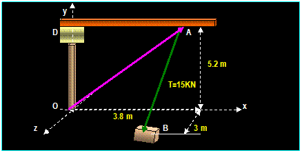
Example:
The
jib crane is oriented so that the boom DA is parallel to the x axis. At the
instant shown the tension in the cable AB is 15 KN. Determine the moment about
each of the coordinate axis of the force exerted by the cable AB.


The
rectangular components of TAB = (15) {1/ [5.22 + 32]1/2
( - 5.2 j + 3 k ] = (15)(- 0.87 j + 0.5 k)
=
- 13.1 j + 7.5 k
Position
vector OA = + 3.8 i + 5.2 j
1 0 0
a)
Moment about x axis = ux . (rOA x T) = │ 3.8 5.2 0 │ = [(5.2)(7.5) ]
= +39 KN-m
0 -13.1 7.5
0 1 0
b)
Moment about y axis = uy . (rOA x T) = │ 3.8 5.2 0 │ = - [(3.8)(7.5) ] = - 28.5 KN-m
0 -13.1 7.5
0
0 1
c)
Moment about z axis = uz . (rOA x T) = │ 3.8 5.2 0 │ = [(3.8)(-13.1) ] = - 49.8 KN-m
0 -13.1 7.5
_______________________________________________________________________________________________
Summary:
The
vector representation of moment about a point is: MA = rA x
F and the vector representation of the moment about the axis is: Ma-a
= [ua-a . (rA x F)] ua-a.


|
|
Lecture 15
Force System Resultant
Moment of a Couple (4.6)
|
|
Moment of a Couple:
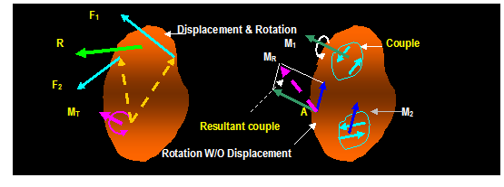
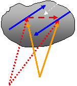
It was
pointed out earlier that a force or a system of forces acting on a rigid body
produces two effects: It moves the body,
and rotates it about an axis. When two forces that are equal in magnitude and opposite in direction act
on a rigid body, they tend to rotate the body without moving it. The
system of forces that produce rotation but not displacement is called a couple. The moment produced by the couple is
called couple moment.


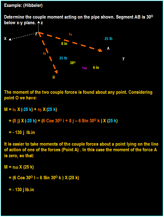
A simple example of a couple consists
of two forces F and F separated by a finite distance. The couple about point A
is:
M = rA
x ( - F) + rB x ( + F ) = (rB
rA) x F
The above
equation is equivalent to: M = (rB rA)
x F where the quantity (rB rA)
is the vector directed from point of action of one force to the point of action
of the other. The effect of the couple is, therefore a moment M that induces
rotation but not translation. It is important to note that M depends on
position vector r = (rB rA)
but not on vector rA or vector rB. This means that the couple has no fixed point of
application and same result would have been achieved if the moment had been
computed about a different point.
r = rB rA
+ F M = rA x (-F) + rB x (+F) = (rB rA) x F
B
- F
rA Moment of couple about O1 Ξ about O2
Moment
of couple is Independent of position
rB
O2
O1
|
|


 O1
O1


Lecture 16 and 17
Equivalent System
Resultant of a Force & a
Couple (4.7, 4.8)
|
|
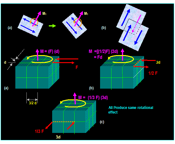
Equivalent System:
The characteristics of a couple
stay the same if:
-
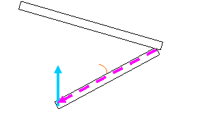
The couple is moved to a position in its original plane (see a).
-
The couple is moved to a plane parallel to its original plane (see b).
-
The magnitude of the force and distance can be changed provided that the moment
Remain the same.
Equivalent System
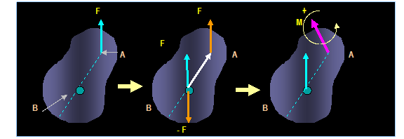
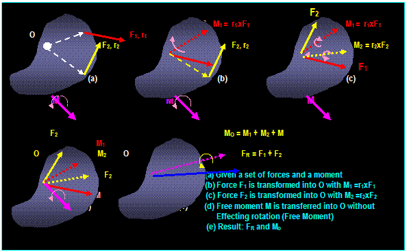
A set of forces and couple moments acting on a body can
be simplified and replaced by an equivalent single force and a single moment.
Similarly, a single force can be replaced by an equal parallel force through a
different point. To
compensate for the move of the force into different location, it is necessary
to add a couple.
Consider a force F acting on a rigid body
at point A.
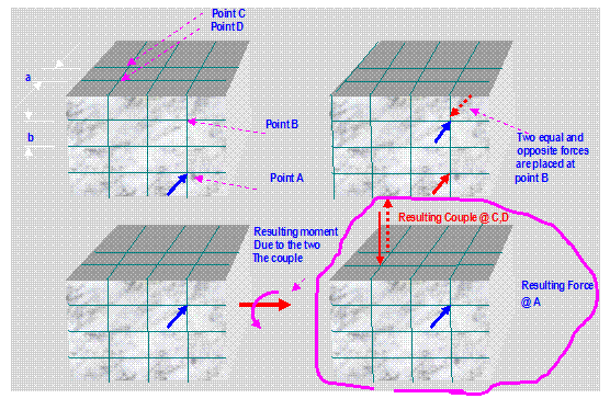
It is desired that the force be moved to another point, say B. Since the concept of
transmissibility allows the force to slide anywhere along its line of action
without altering the external effects on the body, we can move a force equal to
F to point B and attach equal but
opposite force at the same point. As a result, a force F is now applied to point
B along with
a couple formed by F and F. Thus any force acting on a body can be replaced by
the same force at another arbitrary point, provided that a couple of moment of F about A is added. Note that since M is a free vector and can be applied anywhere.


Example
1:
Replace the
force F=100 N acting on point A
by a force acting on point B and a vertical couple acting on C and D as shown
in the figure.


Resultant of a Force and Couple System:
Example
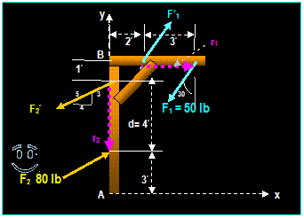
1: (From Hibbeler)
Two couples act on the frame. If d = 4 ft, determine
the resultant couple moment. Compute the result by (a) resolving each force
into x and y components and (b) summing the moments of all the force components
about B.
a) F1 = - 50 sin 30O i - 50cos 30O
j F2 = (4/5)(80) i +
(3/5)(80) j
r1 = 3i r2 = - 4 j
Since: MC = ∑ (r x F)
i j k i j k
MB =
│
3 0 0
│+│ 0
-4 0 │
-50sin 30O -50cos 30O 0 (4/5)(80) (3/5)(80) 0
= (-130 +256)k
= 126 k lb-ft
 Negative because it is opposite to +z Axis
b) MB = F 1y (2) F1y (5) F 2x (1)
+ F2x (5)
MB = 50 cos 30O
(2) 50 cos 30O (5) - (4/3) (80)(1) + (4/5) (80)(1) + (4/3)
(80)(5)
 = 126 k
lb-f
Example
2:
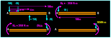
A 100 m beam subjected to the forces
shown. Reduce the system of forces to (a) equivalent force-couple system at A, (b)
equivalent force-couple system at B

 (-)
(-)
a) R = ∑
F = -100 j - 80 j + 150 j 20 j = - 50
j (MR)A = (25i)x(-80j)+(53i)x(+150j)+(100i)x(-20j)
= - (3950 N-m) k
b) Transferring the resultant R to B must be
accompanied by a moment of R to B:
 (+)
(+)
Moment at B due to R = (MR)B = (-100i) x (- 50 j) = (5000 N-M) k
 (-)
(-)
Total moment at B = (5000 k) + (-3950k) = (1050 N-M) k
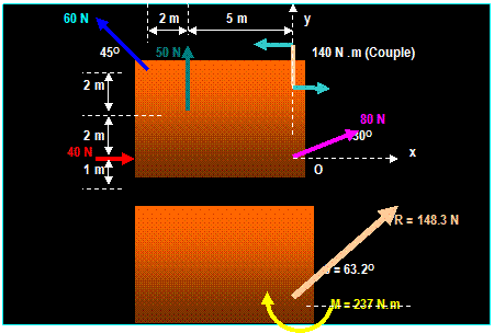
Example
(From Meriam)
Determine the resultant of the four forces at point O
and the couple acting on the plate shown
RX = 40 + 80 cos 30O
60 cos 45O = 66.9 N and: RY = 50 + 80 sin 30O
+ 60 sin 45O = 132.4 N
R = √ (RX2
+ RY2) R =
√ (66.9)2 + (132.4)2 = 148.3 N and:
θ = tan -1 (RX
/ RY ) = tan -1
(132.4 / 66.9) = 63.2O
MO = 140 50 (5 m) + 60 cos 45O
(4 m) 60 sin 45O (7) = - 237 N.m Located at O
Example:
Replace the forces, moment, distributed force and
couple by a force-couple system at A.
 Equivalent force: ½ (20)(8) = 80 N


 20 N/m 8 m F = 60 N

 A 2m M = 200 N.m


 5 m 8 m 2m 5 m 40O
 F = 100 N
F = 60 N
ΣFx = 100 cos
40 i = 76.6 i
ΣFy = - 100 Sin 40 (1/2) (8m) (20 N/m) = -144.28 j
FR = SQRT (76.62 + 144.282
) = 163.35 N @ θ = tan-1 (-144.28 / 76.6)
= -62.04O
 +
+
Σ MR = 200 N.m
(60 N)[4m] (100) sin 40 [5+8+8+5] (80) [8/3 + 5]
= 200 240 1671.25 613.33
=
= 2324.58 N
The equivalent Forces and moments are
shown below:
 MR
= 2324.58 N
FR = 163.35 N
Note that MR and FR
act on A will produce the same external effects at the supports as those
produced by the original force and moment system.
|
|
Lecture 18
Force System Resultant
Distributed Loading (4.10)
|
|
Distributed Loading:
Occurrence: Distributed loading occur in various
structures such as: bridges, slabs, beams, fork lifts, Retaining walls,
platforms and other structures subjected to body weight and/or loads.
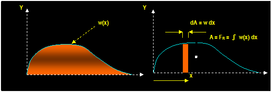
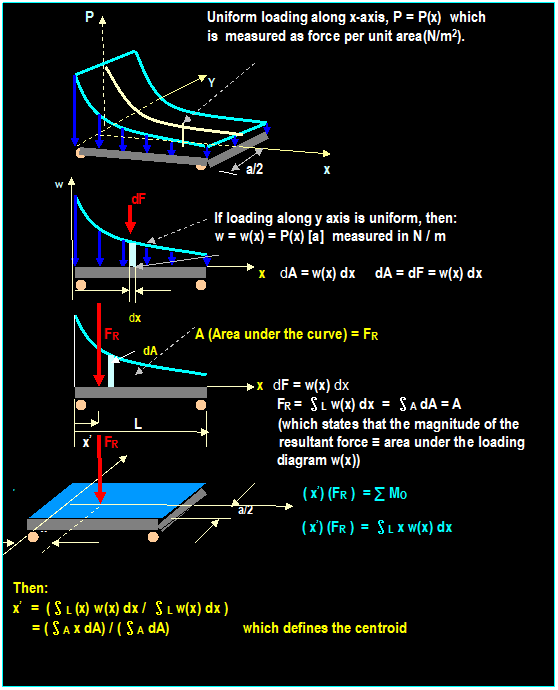
If
the distributed load along the x-axis can be represented by a single force:
F =
Area under the curve = ∫L w dx = ∫A dA
Location
of the force: x0 = ∫ x w dx / ∫ dA


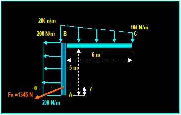
Example: (Hibbeler)
Replace the distributed loading by an equivalent
resultant force and specify where its line of action intersects member AB,
measured from A.


+ ← ∑ FR x = ∑ Fx = (5) (200 N) = 1000
N and: + ↓ ∑ FR
y = ∑ Fy = [(200
+ 100) / 2] (6) = 900 N
FR = √ [(1000)2 + (900)2]
= 1345 N θ = tan-1
(900/1000) = 42O
 MRA = ∑MA = 1345
cos 42O (y) = 1000 (2.5) 300 (2) 600 (3) gives
y = 0.1 m FR = 900 N
F1 = 300N


 F2 = 600N

200 N/m
100 N/m

 B 6 m
B 6 m
x
Example 2:
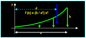
Find the position of the resultant d of the loading
shown below.
F = ∫ w(x) dx = ∫0→a
(b/a2) x2 dx = (1/3)(b/a2) a3 =
1/3 ba
M = (x) ( F )
= ∫0→a x(b/a2) x2
dx =(1/4) ba2
Since d = M / F
Then: d = (1/4ba2) / (1/3 ba) = Ύ a
|
|
Lecture 19
Equilibrium of a Rigid Body
2-Dimensional Free Body Diagram (5.1, 5.2)
|
|
Conditions for Rigid Body:
The necessary conditions
required to attain equilibrium in a rigid body are:
1)
The summation of internal and external forces must be zero.
∑ fi
+ ∑ Fi = 0
2) The summation of all moments about a point must be
zero.
∑ Mfi + ∑ MFi
= 0
Where Mfi
and MFi are the moment
due to internal and external forces respectively.
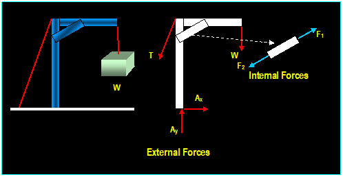
Internal Forces:
Internal
forces are the forces that hold together the various particles forming the
rigid body. They usually appear when a rigid body is dismembered and the free
body diagram is drawn.
External
Forces:
External forces are
the forces that act on the rigid body as a whole. They include: Weight, tension
and reaction forces.

Equilibrium in Two Dimensions:
Free-Body Diagrams:
When a free
body diagram involves a set of unknown reactive forces acting at a point (For
example: reactive forces acting on ball and socket, thrust bearing, hinges,
etc.). To minimize the number of the unknowns, it is often convenient to take the moment about
these forces.
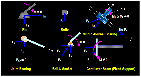
Support Reactions:
Rule of Thumb: If a support prevents translation
(movement) of an object, in a given direction, a force is developed on the body
in that direction. Examples are shown below:

Equations of Equilibrium:
If the free-body diagram of the whole rigid body is
taken, Newtons
law states that all internal forces occur in equal and opposite in direction,
the above equations become:
∑ Fi
= 0 and: ∑ MO =
0
Which
states that, if the rigid body is to be at equilibrium, the sum all external
forces acting on the body and the summation of all the moments due external
forces about a point is zero
Methods of solution:
-
Establish x, y coordinate system.
- Outline the free-body diagram.
- Assume the directions of the unknown forces and moments.
- write the equations of equilibrium ∑ MA = 0 by
choosing point A so that
point o lies on line of action
of two unknown forces. This is done to ensure
the direct solution of the third
force (see figure).
- Write the equations of forces:
∑ Fx = 0 , ∑ Fy =0
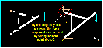
- Orient x-y axis so as to minimize the number of the unknowns (see figure).
- if the
solution yields negative values reverse the assumed directions of the
unknown
Forces and couple moments.
|
|
F1 A F2 B Ax
Pin Ball
Ay By
|
|
|
|
F1
F1
A
Beam fixed to wall
|
|


θ
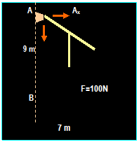
Example:
 +
+
∑ MB = 0 then: (9)
Ax + (7)100 = 0
 Ax = -77.78 Then
AX ←

 ∑
Fx = 0 then
B = 77.78 →

∑
Fy = 0 then: Ay = 100 N
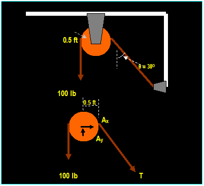
Example: (Hibbeler)
The cord shown supports a force of 100 lb and wraps
over a frictionless pulley. Determine the tension in the cord at C and the
horizontal and vertical reaction at A.


Solution:
Equations
of equilibrium
Σ MA = 0 Then: 100 (0.5) T (0.5) = 0 Then T = 100 lb
Σ Fx = 0 Then: Ax + 100 sin 30o =
0 → Ax = - 50 Then: Ax
= 50 lb ←
Σ Fy = 0 Then: Ay 100 100 cos 30o
= 0 Then: Ay = 187 lb
↑
Example: (Hibbeler)
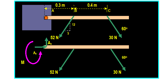
The box wrench is used to tighten the bolt at A. If
the wrench does not turn when the load is applied at B and C, determine the
moment applied at the bolt and the force at the wrench


Solution:
Σ Fx = 0 Then:
Ax 52 (5/13) + 30 cos 60o = 0
Gives: Ax = 5 N
Σ Fy = 0 Then:
Ay 52 (12/13) + 30 sin 60o = 0
Gives: Ay = 74 N
Σ MA = 0 Then:
MA
52 (12/13) (0.3) - 30 sin 60o (0.7) = 0
Gives: MA = 32.6 N-m
Note: We added the unknown moment M because it
is free vector and must be included.
FA = SQRT[(52) +(742)]
= 74.1 N and θ = tan-1
(74/5) = 86.1o
/_
Checking the calculation:
+
Σ MC = 0
Then: 52 (12/13 m) (0.4) + 32.6
N-m 74 (0.7 m) = 0 OK
Most Common Support Reactions:

Example: (Hibbeler)
Determine the reactions at
the pin support A and ball support B

3000 N 750 N
We have three unknowns
& three equations, ΣFx
= 0 Ax = 0
ΣFy
= 0 Then: Ay
+ By (250)
(12 ft) (1/2) (250) (6 ft) = 0
Σ MA = 0 Then:
(6) By (2+6)(750) (0) (3000) = 0 Then: By
= 1000 lb
Substituting into the
first equation:
Ay =
-1000 + (250) (12) + (1/2) (250) (6) Then:
Ay = 2750 lb Ax
= 0
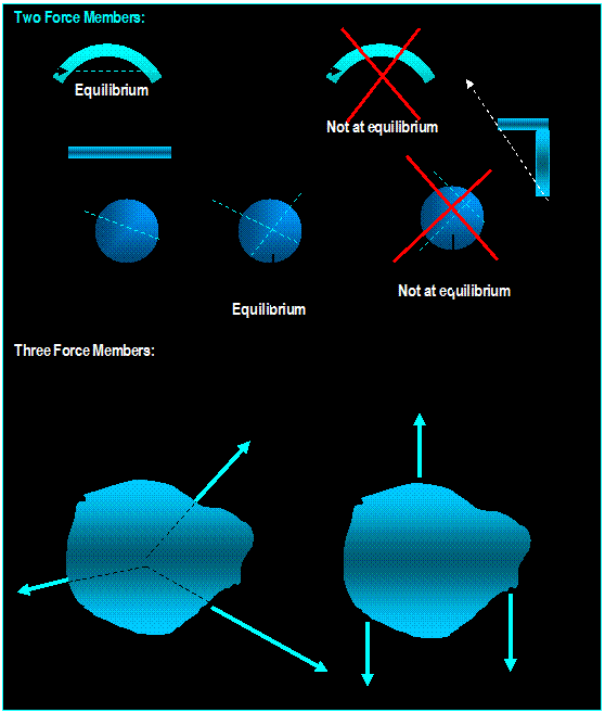
Two and Three Force Members:
Two Force
Members: If a body is held by two forces at equilibrium, the forces must be
collinear, equal and opposite in magnitudes. This requires that the resultant
moment and resultant forces are zero.
Three
Force Members: When a body is held by three forces at equilibrium, the
forces must be concurrent and coplanar, or they must be parallel.
|
|
Lectures 20-22
Equilibrium of a Rigid Body
3-Dimensional Free Body Diagram (5.3, 5.2, 5.3,
5.4, 5.5)
|
|
Equilibrium in three Dimensions:
a)
Vector
Equations of Equilibrium:
The
conditions are: Σ F = 0 and:
Σ Mo
= 0 Where Σ
Mo is the sum of couple moments and moments of all forces
about point O.
b)
Scalar
Equations of Equilibrium:
Σ F = Σ Fx i+ Σ Fy j+ Σ Fz k = 0 Or:
Σ Fx =
0, Σ
Fy =
0 and:
Σ Fz = 0.
Σ Mo = Σ Mx i + Σ My j + Σ Mz k = 0 Or: Σ
Mx = 0, Σ My = 0 and: Σ Mz = 0
Methods of Solution:
a) Example Using Scalar Solution:
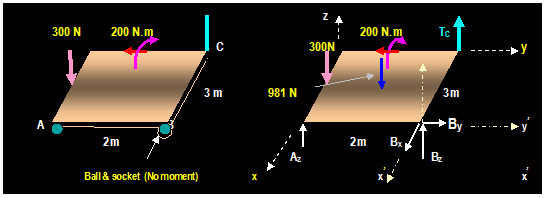
Example: (5.15, Hibbeler)
The homogeneous plate shown has a
mass of 100 Kg is subjected to a force and a couple moment along its edges. If
it is supported in the horizontal plane by means of a roller at A, a ball and
socket at B, and a cord at C, determine the components of reaction at A, B
& C.


Solution:
Unknowns: Az, Bx, By, Bz
and TC ∑ Fx
= 0 Then: Bx = 0 ∑ Fy = 0 Then:
By = 0
∑ Fz
= 0 Then: Az + Bz + Tc 300 N 981 N = 0
(1)
Summing the moments of the forces on the free-body
diagram, with positive along x and y axis yields:
 +
+
∑ Mx = 0 TC (2m) 981 N (1m) + Bz
(2m) =
0 (2)
 +
+
∑ My = 0 300 N (1.5m) + 981 N (1.5 m) Bz (3m) Az (3m) 200
N.m =
0 (3)
Solving (1), (2), (3)
Gives: Az = 790 N Bz = -
217 N and TC = 707 N
b) Example Using Vector Solution:
To determine
the unknown forces take the summation of moment bout a line that passes as many
unknowns as possible:
EXAMPLE: (5.17, Hibbeler)
Let
F = - 1000 j (in the opposite y
direction). Determine the tension in cables BC & BD and the reactions at
the ball and-socket joint A.

FA
= Ax i + Ay
j + Az k
.(reaction at ball-and-socket ,
unknown)
TBC
= TBC [ 6i - 6k) /SQRT (62+62)
TBC
= 0.707 TBC i 0.707 TBC k
(TBC
unknown)
T BD
= T BD (- 3i + 6j 6k) / SQRT
(32 + 62 + 62)
T BD
= - 0.333 TBD
i + 0.666 TBD j - 0.666 TBD k
.( TBD
unknown)
Σ Fx = 0 Ax + 0.707 TBC
0.333 TBD = 0 (1)
Σ Fy = 0 Ay -
0.666 TBD 1000 = 0
(2)
Σ Fz = 0 Az - 0.707 TBC 0.666 TBD =
0 (3)
Summing
moments about point A:
Σ MA = o Or:
r BA X ( F + TBC +
TBD ) = 0
(6 k) X (- 1000 j + 0.707 TBC
i 0.707 TBC k - 0.333 TBD i + 0.666 TBD
j - 0.666 TBD k = 0
Evaluating
the cross products and equating components of i = 0, components of j = 0
(-4
TBD + 6000) i + ( 4.24 TBC 2 TBD
) j = 0 (4,5)
(Note that components of k =0), we have 5 equations and
five unknowns: TBC, TBD, Ax,
Ay and Az.
Then: TBC
= 707 N, TBD
= 1500 N, Ax
= 0 N, Ay = 0 and Az = 1500 N
EXAMPLE: (Hibbeler)
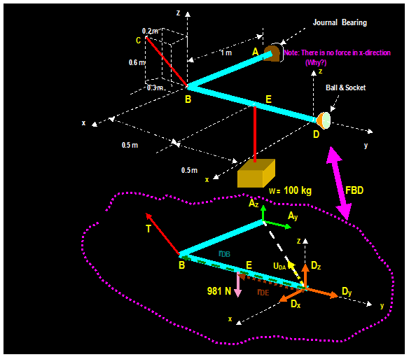
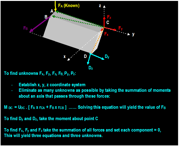
The rod is supported at A by a joint bearing and at D
by a ball-and-socket joint and at B by a cable as shown. Find the tension in
cable BC.


Solution:
There are six unknowns including three force components caused by the
ball-and-socket at D (Dx,
Dy & Dz), two caused by the journal bearing at A (Az & Ay), and one tension caused by the cable (T).
One way to solve the problem is to solve five
equations ( 3 from Σ Fx = 0, Σ Fy = 0 and
Σ Fz = 0 and 2 from Σ MA
= o and Σ MD = o
As an alternative, the tension T at the cable can be
obtained by taking the moment about the line passing through D and A which will
eliminate unknown forces Ax,
Ay, Dx, Dy and Dz
Σ MDA = UDA . (rDB
x T + rDE x W) = 0
UDA = rDA / |rDA| = -
1/√2 i 1/√2 j
UDA = - 0.707 i 0.707 j
rDE = - 0.5 j
W = - 981 k
rDB = - j
T = T( 0.2/0.7) i T(0.3/0.7) j +
T(0.6/0.7) k or:
T = 0.286 T i 0.429 T j + 0.857 T k
Σ MDA = UDA . (rDB x T + rDE
x W) = 0
(- 0.707 i 0.707 j) . [(-
j) x [0.286 T i 0.429 T j + 0.857 T k] + (- 0.5j) x (-981
k)] = 0
(- 0.707 i 0.707 j) . j X [(
- 0.286) Ti + (- 0.857) T k + ( - 0.5j) x (-981 k)] = 0
(- 0.707 i 0.707 j) . (0.286 T k - 0.857 T i + 490.5
i ) = 0
(- 0.707 i 0.707 j) . [(- 0.857 T + 490.5 i) i +
0.286 T k) = 0
(- 0.707i) . (-0.8571T + 490.5 ) i + 0 + 0
- 0.707 (-0.857 T + 490.5) Then: T = 572 N
To Find Dz take the moment about line AB ( DZ = 490.5 N)
Similarly, to find AZ take the moment about
y axis (Az = 0)


|
|
Lecture 23
Structural Analysis
Simple Trusses, the Method of Joints (6.1, 6.2)
|
|
Simple Trusses:
A truss is a
framework composed of straight wooden or metal members joined together by
riveted connections, large bolts or gusset plates to form a rigid structure
known as truss.
Simple Trusses:
Trusses made up of basic triangles put together to form a truss.


Planar Truss:
Trusses that lie in a single plane. They are used to support roofs and bridges.
They start from a single triangular unit and joined together by additional
units.
Assumptions:
- All members are joined
together by pins to
prevent bending of members.
-
All loading is applied at the joints and weight of individual members are
negligible.
-All
truss members are two-force members
which makes them either in tension
or
in compression.


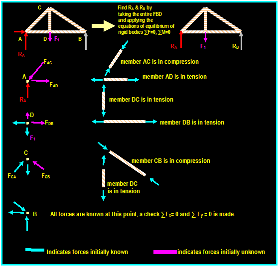
Method of Joints:
Method of
joints consists of applying the condition of equilibrium of forces at each point
of connecting pin in the truss. The method is summarized as follows:
- Draw the free body diagram of any joint where at least one
known load exists and
no more than two unknowns are
present. If this point lies on one of the supports,
it is necessary to find external
reaction at this point by considering
the entire truss
as a free-body-diagram and using
the equations of equilibrium of rigid body to solve
for the external reactions of the truss.
.
-
Assume the member acting on the joints free-body-diagram to be in tension. If
the
answer yields negative number, the member is in compression the correct
sense is
used for the analysis of the
subsequent joint.
- Apply
the two equilibrium equations ∑ Fx = 0 and ∑ Fy
= 0 to solve for the unknown
forces.

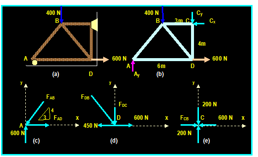
Example :(6.3, Hibbeler):
Determine the force in each member of
the truss shown. Indicate whether the members are in tension or in compression.


 To determine FDC, we can do one of the
following: FDB FDC
a) We can retain the sense of FDB and apply
the equation:
∑ Fy = 0 - FDC (4/5) (-250N) = 0 Then:
FDC = 200
N (C)
450 N 600 N
b) We can correct the sense of FDB and
apply the equation:
From the free body diagram of the entire truss, the
support reactions can be determined by applying the equations of equilibrium:
 ∑
Fx = 0 600 N Cx
= 0 then: Cx = 600 N
∑ MC = 0 -Ay (6m) + 400 (3m) + 600N
(4m) = 0 then: Ay = 600 N
 ∑Fy
= 0 600N 400 N Cy =
0 then:
Cy = 200 N
Joint A: (see fig. (c)):
Three forces acting on pin A: FAB is
compressive (in order to balance the upward force 600N)
FAD is tensile (in order to
balance the x coordinate of FAB)
∑Fy = 0 Then:
600N (4/5) FAB = 0
Then: FAB = 750 N (C)
∑ Fx = 0 Then:
FAD (3/5) (750) = 0
Then: FAD = 450 N (T)
Joint D: (see fig. (d)):
The force in AD is known and it is tensile (why?) so
we only have two unknown forces in joint D. The two forces can be determined by
summing forces in the horizontal direction:
∑ Fx = 0 Then:
-450N + (3/5) FDB + 600N = 0 Then:
FDB = -250 N which
means it acts in the opposite sense to that shown in figure (d) Then: FDB = 250 (T)
∑ Fy = 0 - FDC (4/5) (250N) = 0 Then:
FDC = -200
N (T) or: FDC
= 200 N (C)
Joint C: (see fig. (d)): ∑ Fx = 0 Then:
FCB 600N = 0 Then: FCB = 600 N (C)
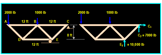
Example: (Beer & Johnston)
Using the method of joints, determine
the forces in each member of the truss shown and determine whether the member
is in tension or in compression.

∑MC
= 0 Then: (2000 lb)(24 ft) + (1000 lb)(12 ft) Ey (6 ft) = 0 Then:
Ey = + 10,000 lb ↑
∑Fx = 0 Then:
Cx = 0
∑Fy = 0 Then: (-20000 lb) - `1000 lb + 10,000 lb +Cy = 0
Then: Cy = -7000 lb = 7000 lb↓
Cx = 0
Joint A:
FDA
= 2500 lb
FDB
FDB
FDA D 4
FDB = FDA
Then: FDB = 2500 (T)
3 FDE = (3/5) FDA
+ (3/5) FDB
D FDE FDE Then:
FDE = 3000 (c)
|
|
Joint D:
1000 lb ∑FY = 0 -1000
(4/5)(2500) + (4/5) FBE =0
A B FBC Then: FBE = 3750
lb or: FBE = 3750 (C)
1500 C
∑ Fx = 0 FBC -1500 (3/5)
(2500) (3/5) (3700) = 0
2500 E Then:
FBC = 5250 lb or: FBC = 5250 lb (T)
D FBE
|
|
Joint B:

Joint E:

|
|
Lecture 24
Structural Analysis
Zero Force Members (6.3)
|
|
Zero force
members are members in
the truss that carry no forces, they are constructed to provide the
following:
- Increase stability and rigidity
of trusses.
- Provide support for future loading
conditions if necessary.
- Support the weight of the truss

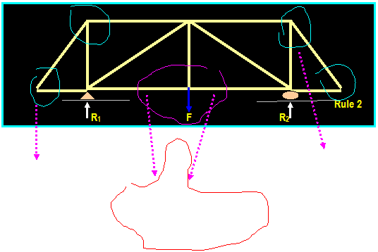
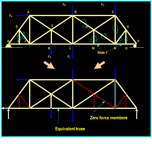
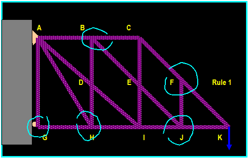
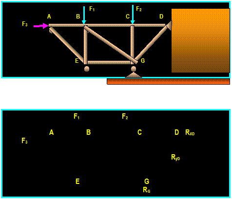
As a general
rule: (Rule
2) (Rule 1)
If three members form a joint in a
truss, two of which are collinear, and if there is no external load or reaction
at the joint, then the third member must be zero force member (Rule 1). If two
members form a joint in a truss and there is no external force or
reaction applied to the joint, the members must be zero force members (Rule
2).
Example: Determine the zero force members in
the truss shown below.

 F1
F1

 F1
F1



 F=0
F=0 F1
F=0
F=0 F1


 F2 F2 ≠ 0

 F2 F3
F2 F3
F1 = F2
= 0 (No external load
F1 = F applied at the joint)
Rule 2 Then: F1 = F2 = F3
= 0
Example:
Determine the zero force members in the truss shown
below.


In the above structure:
- Joint
I, M and O carry three members, two of which lie in the same line.
Since
Joints
I, M and O carry no external loading,
members DI, FM and GO are zero force
members.
- Applying
the same reasoning to joint G and D, we
find that the two joints are in the
Same situation as members O, M and I and,
therefore, members GN and DJ must be
zero
force members.
-
Forces IH = IJ, KI = KL,
OP = ON, NO = NM, GP = GC,
FC = FL, DA = DH, and
MN =
ML.
- Since no
external force is applied at joints M, N, and O, the forces in members ML,
MN, NM,
NO, ON and OP are all equal.
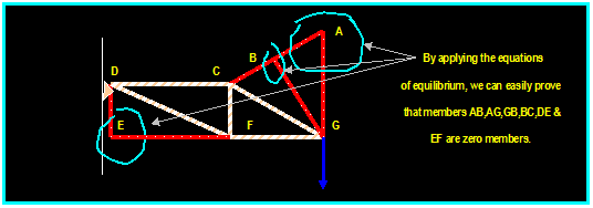
Example:
Determine the zero force members in the truss shown.
In the above:
- Joint
F is has three members, two of its members lie in the same line. Since the
joint has no external loading, member FJ is
a zero force member
- With the elimination of
member FJ, joint J is practically a three member joint,
therefore, member JE is a zero force member.
- Since
member JE is a zero force member, member EB is a zero force member.
- With the elimination of
member EB, joint B is practically a three member joint,
therefore,
member BD is a zero force member.
- Since
member BD is a zero force member, member DH is a zero force member.
- With the elimination of
member DH, joint His practically a three member joint,
therefore, member HA is a zero force member.
- Joint
G has a horizontal reaction force, therefore, member JA is a zero force
member.
Lecture 25
Structural Analysis
Simple Trusses, the Method of Sections (6.4)
|
|
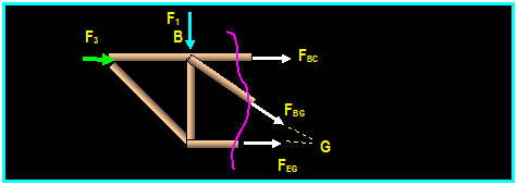
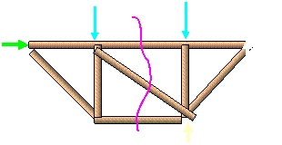
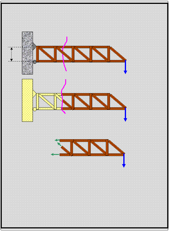
Method of sections
is based on the principle that if a body is in
equilibrium then any part of the body is also in equilibrium. This
method is most useful when only select member forces are to be determined.
Method of Solution:
1)
Draw the Free-body diagram of the whole structure to find the external
reactions
2) Cut the section so that it passes
through the members which are to be analyzed.
In this example, the members
to be analyzed are BC, BG and EG.
3)
Since the isolated cutoff body
is in equilibrium,
the three equations of
equilibrium can be
solved to determine the three forces in members BC, BG
and EG.
Note that , if only the
force in member
BC is desired,
only one equation
of
equilibrium is needed ( ∑M E =
0 ) to yield the value of FBC.


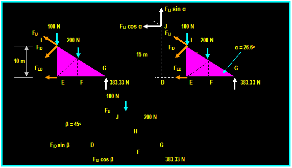
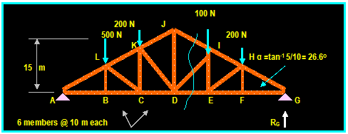
Example:
Determine the forces in members JI,
DI and DE of the truss shown.
Writing the equilibrium equation for the whole
structure: ∑ MA =
0, then:
(RG) (60) = (500)10) + (200) (20) + (100)
(40) + (200) (50) Then: RG = 383.33 N




 200 N
200 N
Force
in member ED: ∑MI = 0
Then:
-
FED (10 m) - 200 N (10 m) + 383.33 N (20 m) = 0 Then:
FED = 566.66 N (T)
Force
in member IJ: We can evaluate the
force FI J by taking the moment ∑ MD = 0 Then:
FI J cos (26.6O)
(15 m) + 383.33 N (30 m) 100 N (10 m) 200 N (20 m) = 0 Then FIJ = -484.63 N =FIJ = 484.63 (C)
Force
in member ID: We can evaluate force FID by taking the moment
about point G:
FID
cos 45O (30 m) + 200 N (10 m) + 100 N (20 m) = 0 Then:
FID = - 188.56 N or: FID = 188.56 (C)
Lecture 26
Structural Analysis
Review of Simple Trusses
|
|
ILLUSTRATIVE EXAMPLE:
Reqd: Use the method of
joints and the method of sections to find the force and direction in member CB.

Using Method of Joints:


 100 N
100 N
 FCB
(Sin 26.57O) = 50 N
FAC FCB ( C)
FCB = 111.8 N (C)


 50
N 26.57O 63.43O


 A B
A B




 100 N
100 N
100 N FAB (T) 100 N 50 N
50 N
Using the Method of Sections:
 CUT
CUT
 100 N E

 FCB
FCB
 (10)
Sin (90-26.57)
 +
+
A FCB (10 Sin 63.43O
) + (100) (10) = 0
FCB = -
111.8 N (T) or: 111.8
(C)
|
|
Lecture 27,28
Structural Analysis
Frames & Machines (6.6)
|
|
Frames:
Frames are
structures composed of joined members that are loaded at any location along
their axis. Unlike simple trusses, frame members are multi force members that
carry three or more forces and they are
not necessarily directed along the axis
of the member.
Method of Solution:
1) Start by taking the
whole frame as
free-body diagram in order to
solve for the external forces acting on the joints and supports.
2) Isolate each part of the
frame (dismember the frame), show all
forces acting on the member
and treat each component as rigid body
under equilibrium and apply the equations of equilibrium to each component.
Do not forget to take advantage of the moment equation to eliminate
unknowns.
3)Since it is not possible
to assign proper
sense to all forces, make an
arbitrary assignment and reverse the sense if it yields negative value. It
is very
important, however, that the
sense of the force
be properly represented in the interacting bodies as
shown in the figure below.


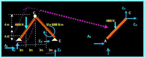
Example:
Determine the forces in member AC.

Taking the
FBD of the whole frame: ∑MA = 0 (EY) (12m)
(6000N.m) (4000N)(3m) = 0, Then:
+
EY = 1500 N ↑
∑ Fy = 0 1500 4000N + AY = 0 Then: AY = 2500 N ↑
Isolating part AC:
∑ FY
= 0 Then: CY + 2500 N 4000
N = 0
 2500
2500
Then: CY = 1500 ↑

∑
MC = 0 Then: 4000 (3m) + AX (8 m)
AY (6 m) = 0
+
Then: AX = 375 N →
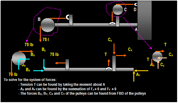
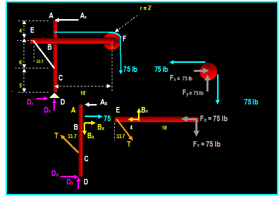
Example: (Beer & Johnston)
In a small frame shown, members EBF
and ABCD are connected by a pin at B and by cable at EC. A 75 lb load is
supported by a second cable which passes over a pulley at F. Determine the
tension in cable EC and the components of the pin reaction at B.
External reactions on the frame involve three
unknown: DX , Dy
and A
∑
Fy = 0 Then: Dy = 75 lb ↑
 + ∑
MD = 0 Then: Ax (15) 75 (12) = 0 Then: Ax = 60 lb ←
∑
FX = 0 Then: DX = 60
lb →
∑
FY = ∑ FY = 0 in the FBD of the pulley. Then Fx = 75 lb → and: Fy = 75
lb ↑
Member EBF and ABCD are connected at B so the forces
acting at point B are equal and opposite as shown. Similarly, The forces
exerted at E and C are equal and opposite and their direction is known.
Member EBF:
+ ∑ ME = 0 Then:
(BY) (4 ft) (75 lb) (14 ft) = 0 Then: BY = 263
lb
 + ∑ MB = 0 Then:
( T cos 33.7O) (4 ft) (75 lb) (10ft) = 0 Then T = 225 lb
∑
FX = 0 Then: ( T sin 33.7O) BX 75 lb = 0
Then: BX = 50
lb
Since the values are found to be positive, the forces
are directed as shown above. The direction of forces on member ABCD are ,
therefore, opposite in sense to that of member EBF.
Checking the calculation on member ABCD: ∑ FX = 0 ? - 60 lb + 75 lb + 50 lb (225 lb) sin 33.7 + 60
= OK
Example: (Hibbeler)
Determine the horizontal and the
vertical component force which the pin at C exerts on member ABCD of the frame
shown.


Identify all two-force members (FB is a two-force
member WHY?)
Step
1: Draw FBD of the entire frame to find
external reactions:
∑ MA = 0 Then: - 981 N (2m) + DX (2.8m) =
0 Then: DX = 700.7 N
∑ FX = 0 Then:
AX 700.7 N = 0
Then: AX = 700.7 N
∑ FY = 0 Then:
AY 981 N = 0
Then: AY = 981 N
Step
2: Isolate Member CF:
∑ MC = 0 Then: - 981 N (2m) FB sin 45O
(1.6m) = 0 Then: FB = -
1734.2 N Or: FB = + 1734.2 acting upward
and to the right.
∑ FX = 0 Then:
- CX + ( 1734.2 cos 45O)
= 0 Then: CX = 1226 N to the left
∑ FY = 0 Then:
CY + 1734.2 sin 45O)
981 N = 0 Then: CY = - 245 N Or: CY = + 245 acting
downward ↓
Disassembling a Frame: (What if the we cannot determine external forces by using the FBD of the
entire structure?)
An Illustrative Example:
Given A Frame consisting of members and pulley as
shown


Civil Engineering Dept.
CE 201 Engineering
Statics
Dr. Rashid Allayla

Internal
Forces
7.1 Internal
Forces:
Internal
forces are the forces that exist within the structure when an imaginary
section is passed through the structure. When the internal forces
are exposed, the forces become external forces.


7.2) Shear and Moment Equations:
Example:
Find internal forces and bending moment at a section 2
m from A


Example:
(Hibbeler)
Determine the internal normal force, shear force and
the moment acting at point B of the frame shown.


EXAMPLE: (Hibbeler)
The beam supports the loading shown. Determine the
internal force, shear force and bending moment acting just to the left of the
external force and just to the right of it.


External forces:
∑ MD = 0
Then: 9 KN-m + (6 KN) AY (9 m) = 0
Then: AY = 5 KN
Segment AB:
∑ FX = 0
Then: NB = 0
∑ FY = 0
5 KN
VB = 0 Then: VB
= 5 KN ↓

∑ MB = 0 - (5 KN) (3 m) + MB = 0 Then MB
= 15 KN.m
+
Segment AC:
∑ FX = 0
Then: NC = 0
∑ FY = 0
5 KN
6 KN
+ VC = 0 Then: VC
= 1 KN ↑

∑ MB = 0 - (5 KN) (3 m) + MC = 0 Then MC = 15 KN.m
+
EXAMPLE:
Find the internal forces and the moments at points B
and C for the cantilever beam shown.
(50)(6/2)


Analysis of External Forces and Moment:
From FBD (b) ∑ MA = 0 Then: - [(50)(6/2) N] (10m)
+ MA = 0 Then: MA = 1500 N-m
∑ FX = 0 Then: AX = 0 and:
∑ FY = 0 Then AY = (50)
(6/2) = 150 N
From FBD (c):
∑ FX = 0 Then: NB
= 0, and: ∑ FY =
0 Then: + 150 VB = 0,
Then: VB = 150 N
∑ MB = 0 Then: MA
Ay (6) + MB = 0,
Then: 1500 (150)(6) - MB = 0

MB = 600 N.m

From FBD (d): ∑ FY = 0 Then: + 150 (50/2) (3/2) VC = 0
Then: VC = 112.5 N
∑ MC=
0 Then: MAAy(9)+(50/2)(3/2)(1) +MC=0,Then:
1500-(150)(9) +37.5+MC =0

MC = 187.5 N.m
 Check the right side:
ΣMC = 0
Then: - (25)(3) (1.5) (25)(3/2)(2) +MC = 0 Then MC = 187.5 N.m
7.2) Shear and Moment Diagrams:
Beam: Is a structural member designed to carry
loading perpendicular to the axis.
Simply Supported Beam: A beam that is pinned at one
end and roller-supported at the other.
Shear Diagram: A graphical representation of shear as
a function of x-axis.
Moment Diagram: A graphical representation of moment
as a function of x-axis.
Sign Convention:


Construction of the Shear and Moment Diagrams:
- Determine the external reactions by
applying the equilibrium equations on the entire
FBD of the beam.
- Cut the beam into various segments
and draw the FBD of each segment.
- Solve for internal forces at the cut
sections by summing perpendicular
forces acting
on each segment to determine shear
force
- Determine the bending moment at the
cut sections.
- Follow positive sign convention as
shown earlier.
- If the computed values of V and M
are positive, the values are plotted above x axis,
and if they are negative, they are
plotted below x axis.
Note:
Internal normal forces are not considered since the
applied loads are generally normal to the x-axis producing only shear forces
and bending moments. Another reason for not considering the normal forces is
that the beams resistance to shear is more important in design than the beams
resistance to normal forces.
Example : (Hibbeler)
Draw the shear and bending moment diagrams of the beam
shown below.

Example:
Draw the shear and bending moment diagrams the beam shown
below.
Problem
2: (Meriam)


Example 3:
Draw the shear and moment diagrams for the beams shown below
(12) + (1/2) [ (1080 - 600) ] (12) 

d

Summary:
To
Construct Shear & Moment Diagrams:
- Solve for support reactions by taking the FBD of the
whole beam and applying the
equations of equilibrium.
- Locate the discontinuities along
the beam.


- Cut the beam into sections between
discontinuities.
-
Construct the FBD of the cut section and apply the equations of equilibrium.

- Plot V vs. M as function of x.

Civil Engineering Dept.
CE 201 Engineering
Statics
Dr. Rashid Allayla

Friction
Friction:
Friction is the force that acts on a body
when it comes into contact with another body. This force, known as the
frictional force, acts tangent to the contacting surface and directed in the
opposite sense to motion or possible motion of the body.
Types of Friction:
- Dry friction: Is the type of friction occurring between two
unlubricated surfaces. The direction
of the friction force always opposes the motion or the impending motion. This type of friction is called
Coulomb Friction.
-
Fluid Friction: Is the friction that exists between
two fluid elements moving at
different
velocities. When there
is no relative velocity between layers of fluid,
friction will not develop
within the fluid.
8.1) Characteristics
of Dry Friction:


Analysis:
If the force P
is increased, the friction force F also increase until
it reaches a maximum value equals FS. If P is further increased, the block starts to slide because the frictional
force can no longer keep the block from sliding. When the block starts to move,
the maximum frictional force drops slightly to lower value FK (called kinetic frictional force) and stays
approximately constant. The reason for the drop is that when F→ FS, the surface peaks shear off and shear
force drops off slightly to FK.
Static Friction:
The frictional force F that
can develop between two surfaces without having the surfaces slide relative to each other is
defined by the equation:
FS = μS N
Kinetic friction:
The frictional force F that develops when two surfaces are sliding on
each other is proportional to the normal force applied on the surfaces and is
directed opposite to the relative motion of the surfaces. This is defined by
the equation:
FK = μK N
Where μS
and μK
are the coefficients of static
and kinetic frictions.
 Coefficient of static friction >
Coefficient of Dynamic Friction
Relates to the magnitude of maximum Relates to the magnitude of
friction force
Friction force that can be
exerted by dry exerted by dry
surfaces when sliding occur
Surfaces when slip is
impending:
f = μK
N where μK is the coefficient of kinetic
f = μS N where μS is the coefficient of friction.
static friction.


Note that:
- The frictional force
F acts tangent to the surface
of contact and directed opposite
to the
relative motion.
- The static
frictional force Fs, the coefficient of static
friction μs and the
coefficient
of the kinetic friction μs are independent of the area of
the surface of contact.
- Both coefficients strongly depend on the
nature of the contact surface (see table)
- When slipping
is about to occur
between two surfaces, the maximum
static force
of friction Fs
is proportional to the normal force so that: Fs = μs N.
- When slipping
start to occur,
the kinetic
frictional force is proportional
to the
normal force so
that: Fk = μk N.
8.2) Solution of Problems Involving
Dry Friction:
Group 1: Equilibrium Problems:
This type of problems require
that the total number of unknowns must be less or equal to the independent
equations of equilibrium. Since the condition of equilibrium requires that no
slipping occur, the solution of Forces must satisfy the inequality FS ≤ μS
N.


Group 2: Impending Motion Problems:
This type of problems require that forces in contact with surfaces
satisfy the equation
FS = μS
N. The total number of unknowns
= number of equilibrium equations + Frictional equations.


Group 3: Impending Motion at Some Point:
This type of problems require that forces in
contact with surfaces will satisfy one of the following conditions: Impending motion, motion or
tipping.


Analysis of the Problem:
In the above problem, the number of unknowns
are: NA + FA + NC + FC + BX
+ BY + P = 7 unknowns
The number of available equations are:
Equilibrium equations: ∑ FX
= 0, ∑ FY = 0,
∑ M = 0
Left
frame: Friction equation: FA
= μA NA
(one equation) and equilibrium equations: ∑FX
= 0, ∑FY = 0,
∑M = 0 (Three equations)
Right
frame: Friction equation: FC
= μC NC (one equation) and equilibrium equations :∑FX
= 0, ∑ FY = 0,
∑ M = 0 (Three equations)
Total: = 8 equations. Since
impending motion for both frames occurring in the same time is highly unlikely,
the choice of which frictional equation to be used depends on the kind of
motion which actually occurs: As P
increases, one of the following possibilities will occur:
a)
Slipping at A and no slipping at
C: Then FA = μA NA and FC
< μC NC
b)
Slipping at C and no slipping at
A: Then FA = μA NA and FA
< μA NA
And the
actual situation can be determined by calculating P and choosing smaller value.
EXAMPLE:
Let W = 100 N, μA = 0.3 and μC = 0.35 Find the value of P that
will cause slipping of the frame shown.
The unknowns: NA, NC, FA, FC, BX, By and P = 7 unknowns
a) Assume Slipping at A and
no slipping at C: Then FA =
μA NA
and FC < μC
NC
FA = (0.3) NA
(1)
Writing the equation of equilibrium for the
right member:
∑FX
= 0 Then: P
- BX FC
= 0
(2)
∑Fy
= 0 Then: NC
BY - 100 = 0
(3)
∑
MC = 0 Then: + (BY) (5 m)
+ (BX) (10 m) P (5) = 0 (4)
Writing the equation of equilibrium for the
left member:
∑FX
= 0 Then: BX FA = 0
(5)
∑Fy
= 0 Then: NA
100 + BY = 0 (6)
∑
MA = 0 Then: + (BY) (5 m)
- (BX) (10 m) (100) (2.5 m) =
0 (7)
Solving
equations 1→7 yield P = 156.25 N
b)
Assume Slipping at C and no
slipping at A: Then FC = μC
NC and FA < μA NA
FC = (0.35) NC
(1)
Writing the equation of equilibrium for the
right member:
∑FX
= 0 Then: P - BX
FC = 0 (2)
∑Fy
= 0 Then: NC BY - 100 = 0 (3)
∑
MC = 0 Then: + (BY) (5 m)
+ (BX) (10 m) P (5) = 0 (4)
Writing
the equation of equilibrium for the left member:
∑FX
= 0 Then: BX FA = 0
(5)
∑Fy
= 0 Then: NA
100 + BY = 0
(6)
∑
MA = 0 Then: + (BY) (5 m)
- (BX) (10 m) (100) (2.5 m) =
0 (7)
Solving
equations 1→7 yield: P = 129.3 N <
156.25
.
Then C will slip before A
Example: (Hibbeler)
The uniform crate has a weight of 196.2 N.
If a force P = 80 N is applied to the crate, determine if it remains in
equilibrium. The coefficient of static friction is μ = 0.3.

Example:
A 150 lb man starts to
climb a 26 ft ladder that weighs 50 lbs. The ladder is placed against smooth
wall with its lower end is 20 ft from the wall. The coefficient of friction
between the ladder and the floor is 0.3. Determine the distance x from the man
to the wall when the ladder starts to slip.


Example:
Two blocks are in top of each other,
the top block is subjected to a force P. If WA = 80 N, WB
= 120 N, μ between block A and B is μs = 0.5 and between B
and the floor is μs = 0.1. What will happen when P increases?

Example: (Hibbeler)
Beam AB is subjected to uniform load of 200 N/m and is
supported at B by post BC. If μB=0.2 and
μC = 0.5,
determine the force P needed to pull the post out from under the beam
200 N/m


A
B
4m 0.75 m
P
0.25 m

 C
C
 800 N
800 N
 AX
FB
AX
FB


 2 m 2 m
 AY NB =400 N NB 400

 FB B
FB B
 0.75 P
0.25

 FC C
FC C
NC
From equilibrium equations: ΣFx = 0 P - FB FC =
0
. (1)
ΣFY = 0
NC 400 = 0
... (2)
ΣMC =
0 - P (0.25) + FB (1) = 0
.
(3)
If Post slips at B: Then FC ≤
μC NC and:
FB = μB NB = 0.2 (400 N) = 80
N
Using this result solving equations 1→ 3 yields:
P = 320 N
FC = 240 N
NC = 400 N
Since FC
= 240 N > μC NC =
0.5 (400N) = 200 N the other case must be investigated.
If Post slips at C: Then FB ≤
μB NB and:
FC = μC NC = 0.5 (NC) (4)
Solving equations 1 → 4 yields: P = 267 N
NC = 400 N
FC
= 200 N
FB = 66.7 N
Since, in this case P is smaller, then post slips at C
first.
EXAMPLE:
A box
1 meter wide and 2 meters high weighs 100 N. The coefficient of
static friction between the box and the floor is μs = 0.5 and
the coefficient of kinetic friction is
μK = 0.3. What is the minimum force that will cause impending
motion of the box?


Example: (Higdon & Stiles)
A 150 lb man starts to climb a 26
ft 50 lb ladder that is placed against a wall and its lower end is 10 ft
from the wall. The ladder is placed on a 100 lb box which is 2 ft high. The
coefficient of friction between the ladder and the wall is 0.20, between the
ladder and the box is 0.35 floor is 0.3
and between the box and the floor is 0.25. Determine how far from the
wall can the man climb before the motion of the ladder impends


Civil Engineering Dept.
CE 201 Engineering
Statics
Dr. Rashid Allayla

Center of
Gravity & Centroid
9.1,9.2) Center of
Gravity, Center of Mass & Centroid for a Body:
Since a body consists of infinite number of
particles, the center of gravity of the body is defined as the single equivalent weight that
can represent all particles in the body.
If the body is homogeneous and gravity is constant in magnitude and
direction, the center of gravity would coincide with the center of mass.


Since the
rigid body consists of infinite number of dV, the center of gravity of the
whole body is the integral of the individual center of gravies of dVs. If x,
y and z are the location of the COG of dV, then:
XG
( Σ Wi ) = Σ ( xI ) ( Wi
)
 = dW
= dW
∫ x γ dV
∫ y γ dV
∫ y γ dV
XG = _________ YG = ________ ZG = _________
∫γ dV ∫γ dV ∫γ dV
Where γ is the specific weight of
the body (dW/dV). If the density of the body is defined as ρ = γ / g where g is the gravity. The
center of mass is defined as:
∫ x ρ dV ∫ y ρ dV ∫ y ρ dV
XG = _________ YG
= ________ ZG = _________
∫ρ dV ∫ρ dV ∫ρ dV
Centroid of a Body:
Centroid is
defined as the geometric
center of the body. If the body is uniform and homogeneous in density,
the term γ drops out of the
equation. The equation of the centroid is determined by summing the moments of
the elements about the coordinate axis.
Centroid of a volume:
∫ x dV ∫ y dV ∫ y
dV
XV
= _________ YV =
________ ZV
= _________
∫ dV ∫ dV ∫ dV
Where ∫ is taken over
the volume V.
Centroid of an Area:
∫ x dA ∫ y dA ∫ y
dA
XA
= _________ YA =
________ ZA
= _________
∫ dA ∫ dA ∫ dA
Where ∫ is taken over
the area A
Centroid of a Line
∫ x dL ∫ y dL ∫ y
dL
XA
= _________ YA =
________ ZA
= _________
∫ dL ∫ dL ∫ dL
Where ∫ is taken over
the line L

Example on Center of Gravity of an Area:
Example :
(Hibbeler)
Locate the Centroid of the area shown.
Example: (Hibbeler)
Locate the X coordinate of the shaded area bounded by
the two curves y = x & y = x2.


Example on Center of Gravity of a Line:
Example: (Hibbeler)
Locate the Centroid of the rod bent into the shape of
parabolic arc.


9.3) Composite Bodies:
Example:


Example: (Hibbeler)
Locate the Centroid of the wire
shown:


EXAMPLE:
Determine the
y & z locations of the center of gravity of the object shown.


Example on Center of Gravity of Volumes:
Example: (Hibbeler 9.6)
Locate
the y axis of the centroid for the paraboloid of revolution, which is generated
by revolving the shaded area shown: The equation of the curve is: z2 = 100 y


 Choosing an element having the shape of thin disk with
thickness (dy) and perpendicular to the axis of revolution with radius r = z.
The area of the element is πz2 and
its thickness is dy. The elemental volume, therefore is: dv = (πz2)
(dy) and its centroid is located at y = y
Integrating
to find the centroid of the paraboloid:
∫ y dV ∫ y = 0 → 100
[y (πz2 )] dy 100 π ∫ y = 0 → 100 y2 dy
yc
= -------------- = ------------------------------- --- =
-------------------------------------
= 66.7 mm
∫ dV ∫y = 0 → 100 [(πz2 )] dy ∫ y = 0 → 100 y
dy
Example:
The
radius of the truncated cone of circular cross section is given as a function
of x by the equation r = 1 +0.25 x.
Determine the coordinate of its centroid.


Because
of axial symmetry shape, the centroid lies on the x axis. We will determine the
x coordinate of the centroid using the elemental volume:

 r
r

 x
x


 dV = π r2 dx
= π [1
+ 0.25 x ]2 dx
dx
 ∫ x dV ∫ 0 → 4 π x
[1 + 0.25 x ]2 dx
xc
= _______ = ___________________
4 ft
∫ dV
∫ 0 → 4 π [1 + 0.25 x ]2 dx
xc
= ∫ 0 → 4 [ x + 0.5 x2
+ 0.063 x3 ] dx / ∫ 0 → 4 [1 + 0.5
x + 0.063 x2 ] dx
= ( 0.5 x2 + 0.167 x3
+ 0.016 x4 ) / ( x + 0.25 x2 + 0.021 x3)
= (8
+ 10.688 + 4.096) / (4 + 4 + 1.344) = 2.438
ft
Summary:
To locate the center of gravity, center of mass, Centroid of
volume, Centroid of area or Centroid of length of composite section:
- Calculate the respective centers of gravity or Centroid
of individual elements of the
composite section.
- Find
the components of center of gravity or
the Centroid of individual elements of
composite section.
- Assign
a negative sign to the area of the cut section.
- Apply
the moment principle XC N = x1 N1 + xn Nn where N
represents gravity, mass
volume, area or length of composite section.
- The X,
Y and Z component C.O.G. or Centroid of the composite section calculated
using
the above equations.

Civil Engineering Dept.
CE 201 Engineering
Statics
Dr. Rashid Allayla

Moments
of Inertia
10.1) Definition:
Given an area A, the moment of inertia of the differential
area dA is defined as:
Ix
= ∫A y2 dA
or, in general: Ix = ∫A y2 f(x)
dx
Where f(x) is a function to be
determined in terms of x.
Iy
= ∫A x2 dA
or, in general: Iy = ∫A x2 f(y)
dy
Where f(y) is a function to be
determined in terms of y.


EXAMPLE:
Determine the moment of
inertia Ix and Iy of the triangle shown:


To evaluate Ix
determine the moment of inertia of the small strip about x axis:
(Ix)element
= ∫element
y2 dA
y
= ∫0 (y2) [dydx]
h
Ix = ∫0 1/3 y3 dx
h
h
Ix = ∫0 1/3 [(h/b) x]3
dx = 1/12 (h/b) x4 │= 1/12 b h3
0
To evaluate Iy
determine the moment of inertia of the small strip about y axis:
 Iy = ∫A
x2 dA Since: dA = y
dx and y/x = h/b or y =
(h/b) x , then:

Iy = ∫A
x2 (ydx)
b
b
Iy = ∫0 x2 [(h/b) x]dx = Ό x4 (h/b) │= Ό h b3
0
Example: Hibbeler
Determine the moment of
inertia for the area bounded by the two functions y = x and y = x2
using: 1) horizontal elemental area and 2) Vertical elemental area.


1) Using horizontal
elemental area: dA = (x1 x2 ) dy
1
1
Ix = ∫
y2 dA = ∫ y2 (x1 x2 ) dy = ∫ y2 (√y
y ) dy = 2/7 y7/2 Ό y4 | = 0.0357 m4
9
0
2) Using vertical
elemental area: dA
= (y2 y1 ) dx
, use the parallel-axis theorem (SEE NEXT TOPIC):
dIx = [ dIx] + [ dA ( y )2]
where: dIx is the
moment of inertia about the center of gravity of the elemental area and y
is the distance of the center of gravity of the elemental area from the x axis,
then:
b

 h3
h3
 dIx
= [1/12 dx ( y2
y1 )3] + [( y2 y1 ) dx] [( y1
+ ( y2 y1 ) / 2 )2]
=
1/3 ( y23 y13 ) dx
h
= 1/3 (x3 x6 ) dx
Then: b
1
Ix = 1/3 ∫(x3
x6 ) dx = 1/12 x4 1/21 x7 |
= 0.0357 m4
9
10.2) Parallel Axis Theorem for an area:
The moment of inertia in terms of x coordinate system was
found to be:
Ix = ∫A
y2 dA and: Iy = ∫A
x2 dA
If y = y + dy and x = x + dx where y and x is the
coordinates of dA relative to the xy axis (passing
through the center of gravity of the area A), then:
Iy = ∫A
(x + dx)2
dA = ∫A
(x) 2 dA +2dx∫
x dA + dx2
∫A dA
= 0 because ∫ x dA = xG ∫ dA = 0 (since xG = 0)
Ix = ∫A
(y + dy)2
dA = ∫A
(y) 2 dA +2dy∫A
y dA + dy2 ∫A dA
Therefore:
Ix
= Ix + A dy2 and:
Iy = Iy + A dx2
Which states
that the moment of inertia for an area about a given axis is equal to the
moment of inertia of the area about an axis passing through its own centroid
plus the product of the area and the square of the distance between the two
axis.


10.5) Moment of
Inertia for Composite Areas:
Method:
1) Divide the composite area into parts of easily determinable moments of
inertia.
2)
Determine the moment of inertia of
each member and use the method of parallel-axis theorem to determine the moment
of inertia about a given coordinate system.
3)
Sum the results.
Illustrative Example:
Determine the moment of
inertia for the beams cross-sectional area shown about the x and y centroidal
axis.

Rectangle A AA
y2CG
Ix = Ix
+ A dy = 1/12 (100)
(300)3 + [(100) (300)] (200)2
= 1.425 x 10⁹
mm4
Iy = Iy
+ A dx = 1/12 (300) (100)3
+ (100) (300) (250)2
= 1.90 x 10⁹
mm4
Rectangle B
Ix = 1/12 (600) (100)3 = 0.05 (10)9
mm4
Iy = 1/12 (100) (600)3 = 1.8 (10)9
mm4
Rectangle C
Ix = Ix + A dy = 1/12 (100) (300)3
+ (100) (300) (200)2
 = 1.425 x 10⁹
mm4
300-50
Iy = Iy
+ A dx = 1/12 (300)
(100)3 + (100) (300) (250)2
= 1.90 x 109 mm4
Summation: Ix = 2.9
(10)9 mm4


![]()
![]()
 Length: Designated by the letter L (cm,
mm, m, km, inch, ft, mile)

![]()

![]() Solution: Mass Acceleration Force
Solution: Mass Acceleration Force![]()


![]()


![]()

![]() 25o
25o![]() A = 40 N
A = 40 N![]()
![]() 20o
20o![]()
![]() Drawing the system using triangular rule and applying the
law of cosine: A = 40 N
Drawing the system using triangular rule and applying the
law of cosine: A = 40 N
![]() 25O
25O  R2 = A2 + B2 2 AB Cos [β)]
But: β = 180-25=155
R2 = A2 + B2 2 AB Cos [β)]
But: β = 180-25=155![]() B=60 N R
B=60 N R![]() = (402)
+ (602) 2 (Cos 155)
β
= (402)
+ (602) 2 (Cos 155)
β ![]()
![]()
![]() θ
α
= 97.7 N
θ
α
= 97.7 N

![]()
![]()
![]()
![]()
![]()
 Solution: 20 lb 30o
![]() Force
Triangle: R α α
Force
Triangle: R α α 20 lb
P =14 lb
20 lb
P =14 lb![]()

![]()
![]()


 P = 14 β
![]() R α 30o
R α 30o 

![]()

![]()
![]()
![]()
![]() In
order to obtain the resultant of a set of coplanar forces, each force is
resolved into x and y components and then added algebraically to obtain the
resultant. In the figure below, F1, F2 and F3
are a set of coplanar forces. In Cartesian vector notation, the forces are
written as
In
order to obtain the resultant of a set of coplanar forces, each force is
resolved into x and y components and then added algebraically to obtain the
resultant. In the figure below, F1, F2 and F3
are a set of coplanar forces. In Cartesian vector notation, the forces are
written as ![]()
![]()
![]()
![]() F1 F2
F1 F2
![]() F3y F3x
F3y F3x
![]()
![]()
![]() )
)

![]()
![]()
![]()
![]()
![]()
![]()
![]()


![]()
![]()
![]()
![]()
![]()
![]() F2 F1
F2 F1![]()

![]() F4
F4![]() F3 F1 Cos
30 i
F3 F1 Cos
30 i![]()


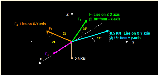
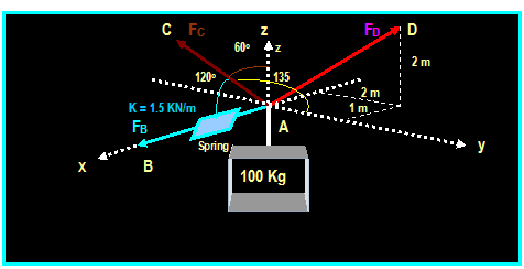


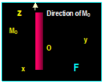
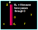


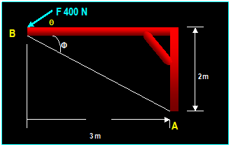

![j0311556[1]](CE_201_files/image240.gif)


