5. Cathodic Protection

5.11 Design Curves


Design Curves

Design curves can be developed to directly read the resistance of multiple pre-packaged anodes in a specified soil resistivity. Below is the procedure:

The following data is needed:

1. resistivity of the soil 1000 ohm-cm
2. backfill column dimensions 0.7081' x 2.333'
3. number of anodes per bed 5, 10, 15, 20, 25 and 30
4. spacing 10', 15', 20', 25' and 30'
   
The following equation is used to calculate the resistance of multiple vertical anodes
      
where R = resistance of a vertical anode to earth (ohms)
P = resistance of backfill material for soil
L = length of the anode (ft)
N = number of anodes in parallel
S = spacing of anodes in ft
Solution
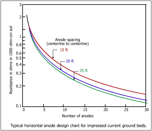
Perform calculations using the above equation. First perform calculations for 10 anode bed with 10 ft spacing and repeat calculations for all values of different spacings (5, 10, 15, 20, 25 and 30). Again repeat calculations for 10, 15, 20, 25 and 30 ft spacing (for all combinations of N and S and tabulate the results as shown below:


Number of Anodes

Anode Spacing

10 15 20 25 30
5 X X X X X
10 X X X X X
15 X X X X X
20 X X X X X
25 X X X X X
30 X X X X X

Plot the data on a semi-log graph paper. A typical design chart is shown below.

How to use the design curve:

The basis of the design curve (conditions): The above diagram is based on a definite galvanic anode size (5" x 5" x 20.5") buried in a backfill (5 ohm-cm) resistivity. The internal resistance calculated for the anode was 0.1076 ohm. For instance, assume that it is desired to calculate the resistance of 15 anodes parallel at 25 ft spacing in a soil of 300 ohm-cm resistivity. Proceed as shown below:

  1. First determine the parallel resistance of 15 anodes at 25 ft spacing from the chart (~ 42 ohms). The resistance in 300 ohm-cm soil would be 0.42 * 300/1000 = 0.126 ohm.

  2. To this resistance add the internal resistance of galvanic anode determined before which was 0.1076 ohm and divide by the number of anodes in parallel (0.126 + 0.1076/15 = 0.133 ohm)

  3. The design curves can be made for different types and dimensions of anodes for both impressed current and galvanic anodes. They are a good time saving device for cathodic protection engineers.