| 5. Cathodic Protection | |
|
5.5 Soil Resistivity Survey |
|
Soil Resistivity Survey
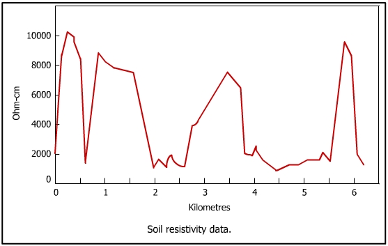
A soil resistivity profile is shown in figure.
The four pin method and soil box method for determination of soil resistivity have been discussed in the previous sections. The areas of low soil resistivity are the hot areas where the current is likely to leave the pipe. It may be recalled that corrosion proceeds when electrons leave and the structure is protected where electrons enter the structure. The areas of low resistivity are marked in the profile. Above a soil resistivity of 10,000 ohm-cm, the soil becomes progressively less corrosive and below this limit, it becomes progressively more corrosive, reaching dangerous corrosive levels beyond 500 ohm-cm.
Potential Survey
The structure-to-soil potential is measured along the distance of the pipeline to find the anodic areas and hot spots. The two methods of making this measurement have been described earlier. It is expected that the anodic areas would have potential around -0.8 volts with respect to Cu-CuSO4 electrode adjacent to the anodic areas. Figure shows a typical potential survey profile. The peaks in the profile represent the hot spot or the anodic areas. Figure shows the limit of protection of coated pipeline.
The peaks showing more negative potential are the hot spots. The task of identifying hot spots is made simpler by super-imposing the soil resistivity and pipe-to-soil potential data, creating a composite profile. The shaded areas (low soil resistivity and more negative potential peaks) spotlight the hot areas. The two surveys shown above are critical for designing the cathodic protection systems.
|
|