| 5. Cathodic Protection | |
|
5.4 Important Measurements in Cathodic Protection [3/3] |
|
Measurement of Structure to Soil Potential
Measurements of structure to soil are helpful in location of a possible corrosive areas in a metallic structure such as the pipeline. The corrosive areas are indicators of current flowing from the structure to the soil. The natural potential which is created by an electrolytic cell of which an electrode consists of a buried steel pipe and the other consists of a Cu-CuSO4 half cell is normally -0.55 volts. In such a cell, the reference half cell acts as as the cathode, whilst the steel pipe acts as anode. The potential survey is therefore extremely important to determine the state of the buried pipe with respect to the surroundings. Two methods are used:
Single-electrode method
Two-electrode method
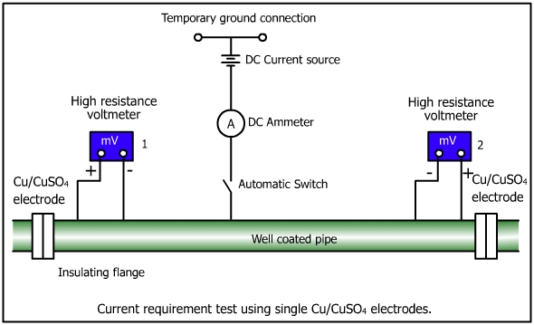
1. Single-electrode method
Figure below illustrates the basic technique.
The positive terminal of the impedence voltmeter is connected to a standard Cu-CuSO4 electrode and is negative to the pipe. In this technique, a long conduction reel is used. The reference electrode is moved along the surface of the earth over the pipe at a uniform distance. The reference electrode should be in contact with the some dampness for connectivity. The pipe-to-soil potential are recorded as shown in line 1. The voltage difference between consecutive readings is shown in line 2. A large difference shows a greater possibility of corrosion. The data plotted as pipeline length vs pipe-to-soil potential ( Cu-CuSO4 electrode) is called a pipe-to-soil potential profile.
2. Two-electrode method
This method utilizes a pair of copper sulphate electrodes instead of a single Cu-CuSO4 electrode. The potential readings are obtained by leap frogging the double electrode along the pipeline or any structure as shown below.
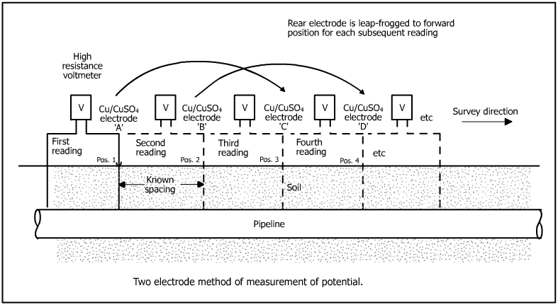
The survey is started by placing the electrodes at position I on the surface and electrode B at the next location over the pipeline. The potential difference between the two positions is now recorded along with polarity of the forward electrode. The electrode A at position 1 is leap frogged to position 3 and the potential between the measured again. The procedure is repeated along the full length of the pipe.
The following method is adopted to determine the value of the actual pipe-to-soil potential.
Measure pipe-to-soil potential at position1.
Measure soil-to-soil potential between positions 1 and 2.
Add algebraically to the readings at position 1 to obtain the pipe-to-soil potential.
Measure soil-to-soil potential between position 2 and 3 and add algebraically to position 2 to obtain the pipe-to-soil potential at position 2.
Figure below illustrates the principle of pipe-to-soil potential measurement to detect corroded areas.
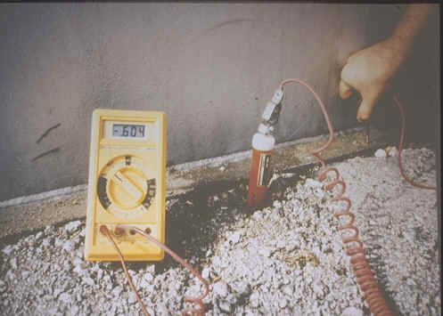
A picture of actual measurement of corrosion potential using Cu-CuSO4 electrode is shown below.
|
|