| 5. Cathodic Protection | |
|
5.4 Important Measurements in Cathodic Protection [2/3] |
|
Measurements of Soil Resistivity
There are several methods of measurement. Only the Weener four pin method is being described below as it used most commonly.
1. Weener 4-pin method
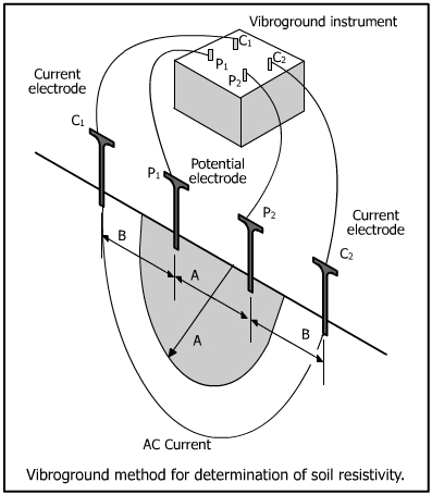
Four steel pins are arranged equidistant in a straight line in soil as shown below.
An AC current is made to flow between the two outer pins P1 and P2 which represent the IR drop through a segment of earth. The average soil resistivity is measured to a depth A when the distance between the pins B is equal to A as shown in the figure.
The soil resistivity per cm3 (ohm-cc) is calculated as
| Soil resistivity = 2 p A R |
| where |
| A = distance between pins P1 and P2 |
| R = instrument reading |
The expression for P is 191.5 AR where A is expressed in ft. If the pins are placed further apart, the soil resistance is measured to a greater depth. The instrument reading R must be multiplied by a k factor from the table given below for various depths.
Table 5.7: Values of k factor.
|
Normal pin spacing |
Actual spacing |
Multiply by |
| 2'-6" | 2'-7" | 500 |
| 5'-6" | 5'-3" | 1000 |
| 7'-6" | 7'-10" | 1500 |
| 10'-6" | 10'-6" | 2000 |
| 15'-6" | 15'-9" | 3000 |
The vibroground instrument works on 'null balance' principle. The voltage drop developed by a current flowing through the unknown ground resistance is measured by comparing it to a portion of the voltage drop developed by the same current flowing through a calibrated potentiometer.
Remember, P = 191.5 AR (where A is in ft)
| When |
| distance = 1 ft, k = 191.5 |
| distance = 2ft, k = 383 |
| distance = 3ft, k = 574.5 |
2. Using a Soil Resistivity Box
A vibroground instrument may be used with a soil box as shown in figure.
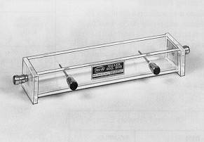
The soil box is made of perspex. The size is 8'-1/2" long, 1'-1/2" wide and 1'-1/4" deep. The volume is 230 cc. The end plate of the box acts as current terminals and the inside contact plates as potential terminals. The box is filled with required soil which is packed firmly. The metal plates are of 1-3/8" x 1" size whereas the electrodes P1 and P2 are metal pins of 1-1/2" length, 1/32" diameter and located 1-3/4" from the box end. The sample of soil is kept in the box with a little moisture and the connections are made with vibrogram. The reading of the vibrogram is directly equal to the reading of the sample in ohm-cc.
|
|