
Pd = ? (tpi – teeth per inch)
Hint: Minimum number of teeth to avoid interference for pinions having 20° pressure angles is 18
Np = ?
![]()
NOTE: Remember, Ng must be an integer, so round-off the value to the closest integer

&
 (rpm)
(rpm)
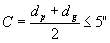
![]() (in.)
(in.)
&
![]() (in.)
(in.)
 (in.)
(in.)
![]() (fpm – feet per minute)
(fpm – feet per minute)
![]() (lb.)
(lb.)
![]() (in.)
(in.)
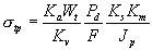 (kpsi)
Based on a reliability of 99%, the computed stress can be compared directly with the allowable stress shown in fig. (14-2) to find the required Brinell hardness for the pinion teeth and call it ‘x’
x = ? (BHN)
![]() (kpsi)
(kpsi)
For the value calculated above, find the required Brinell hardness from fig. (14-2) and call it ‘z’
z = ? (BHN)
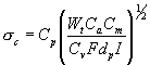 (kpsi)
Compare the computed stress with the allowable contact stress in fig. (14-3) and find the required surface hardness, call this hardness value ‘y’
y = ? (BHN)