Machine Design - II (ME 308 Lab)

Shaft Design - Project # 1


Term 992

Steps # 1 & 2

  1. Using the following equation, calculate input torque:
  2. wpe1.jpg (1761 bytes)

    lb.in.


    Where:

    P is power in HP

    n is speed in rpm

  3. Draw the torque diagram based upon this value of T

wpe2.jpg (7113 bytes)


  1. Solve for tensions T1 & T2 using the following relations
  2. Where:

    T is torque in lb.in. from above

    r is the radius of the pulley in inches


  3. Calculate the radial and tangential forces on the gear
  4. Tangential force on the gear Ft = T1-T2 lb.

    Radial force on the gear Fr = Ft Tan f lb.

    Where:

    f is the pressure angle = 20°


  5. Perform a complete force analysis on the shaft in the y and z directions to determine the resultant reactions at the bearing locations
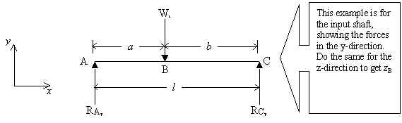
  6. Resultant reaction is given by

    lb.

  7. Using equation (11-9) from the text book, calculate the rated force for each bearing:
  8.  

    wpe3.jpg (3556 bytes)

    ………………. Eqn. (11-9)


    Where:

    FR is the Catalog Load Rating

    FD is the Design Load*

    LD is the Design Life in Hours = 25000 Hrs.

    nD is the Design Speed (given in rpm)

    LRnR is the Rated Life = 106 rev.

    R is the Reliability = 95%

    a for Ball Bearings = 3

    * for the values of FD, use the values of the resultant reactions calculated for locations B & D in step 5 of the lab-sheet, i.e. RB & RD

  9. To calculate C, use the following equation:
  10. C=A.F. ´ FR

    Where:

    A.F. is the Load-Application Factor - use table (11-6)


  11. Select Deep Groove Ball Bearings for the bearing locations B & D on the shaft using table (11-3). Use the value of C, calculated above to select the bearing and note down all bearing data


NOTE:


  1. Draw the shear force and bending moment diagrams in the y and z directions and the resultant bending moment diagram with a free hand sketch of the shaft