King Fahd University of Petroleum & Minerals Department of Mechanical Engineering ME 308 (Machine Design – II) Lab 2nd Semester 1999-2000 (Term 992) Project # 1 – Shaft Design |
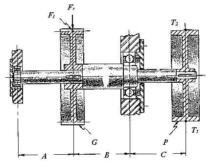
The shaft shown in the figure is to be designed from the standpoint of strength and rigidity. Power is to be supplied to the pulley (P) by means of a flat belt and power is taken from the shaft through spur gear (G). The shaft is supported by two deep groove ball bearings.
The following information has been established:
Horsepower = 10 (steady load conditions)
Speed of the shaft = 900 rpm
Material of the shaft should be Hot Rolled AISI 1035
Diameter of the pulley = 10"
Pitch diameter of the gear = 10"
Weight of the pulley = 30 lb.
Weight of the gear = 30 lb.
Ratio of belt tensions T1/T2 = 2.5
Gear pressure angle (f ) = 20°
The pulley and gear are assembled with square keys and press fits
Dimensions A = B = C = 6"
Safety factor = 3
The belt forces are perpendicular to the paper with the tight side being T1 and the slack side being T2
The tangential force on the gear is Ft and the separating force is Fr
Ft is perpendicular to the paper
The bearings are assumed to have a life of 25000 hours and a reliability of 95%
The following rigidity limitations have been imposed:
For the shaft, do the following: