sequential circuits

Combinational logic is useful for interesting operations like decoding, encoding, addition and subtraction.  However, sequence of operations are cumbersome to handle using combinational logic methods.

Combinatorial logic interconnected with storage elements gives rise to sequential circuits.

In combinational circuit, the output is only a function of all inputs and given any combination of inputs, it is always possible to predict the output.  In sequential circuit, the output is not only a function inputs but history of the input changes.


storage elements

Storage can be constructed logic with delay, such as a buffer by connecting the output to the input.  The signal must not undergo inversion in the loop or the system will be unstable or astable.

An important consequence of this type of feedback, called positive feedback, is that the behaviour of the system is highly dependent on propagation delay of of the gates and timing of the input changes.


synchronous circuits

In asynchronous sequential circuits, input changes at any time may result in the any of of the outputs or internally stored information (called state) to change.  Such circuits are difficult to design because of dependence on propagation delays and their interaction with timing of input changes.

A synchronous sequential makes use of clock signals so that the storage elements (and outputs) only change at discrete instants of time in relation to the clock signal.  Clocked synchronous circuits provide some degree of independence on timing variations related to gate propagation delays.


latch

A storage element maintains binary state indefinitely (as long as power is applied), until directed by an input signal to switch to its other state.

The simplest latch, also referred to as the SR latch has two inputs and two outputs and can be constructed from two NOR gates as shown.

The behaviour of the above latch in can be illustrated using the following timing diagram (unlike combinational circuits, sequential circuits are a function of time) as shown below:

Note that when S and R simultaneously change from their asserted state to their deasserted states, the flip flop enters an unstable state when its outputs oscillate between two binary states indefinitely.

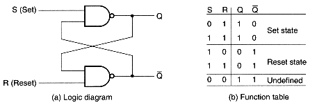
An alternate form of the SR latch, in this case the set and reset signals active low, can be constructed using NAND gates as follows:
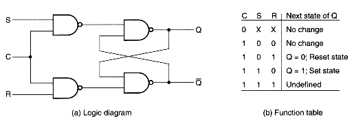
One way to prevent the system from becoming unstable is by means of gating the set and reset inputs using a control input.
Another way of eliminating the undesirable unstable state is by means of making sure that both set and reset signals are never active at the same time giving rise to a what is called a D latch.


flip-flops

In the case of a latch with control input, the when the control is enabled, the latch is in transparent mode, that is its output changes its state according to the set and reset states.  During this transparent mode, it is still possible for the outputs to become unstable if both set and reset inputs change from asserted to deasserted states simultaneously.

We avoid this problem using master-slave  flip-flop arrangement as illustrated below:

Note that it is impossible (well, almost) for both the set and reset inputs to be asserted for the slave latch on the right when its control is enabled because the control of the master latch on the left is disabled at this time.


J-K flip-flop

A modified version of the SR flip-flop which eliminates the unstable oscillation  and indeterminate behaviour is the JK flip-flop.


edge-triggered flip-flops

The control signal in master-slave arrangement enables the master latch to be in transparent mode while it is high.  Thus the flip-flop is sensitive to inputs to the master for all the time its control signal is enabled.

In the case of edge triggered flip-flips, the control pulse is ignored while it is at a constant state and changes occur only during a transition of the clock signal.

The above is an example of a positive edge triggered D-type flip-flop.


flip-flop symbols


characteristic tables

The characteristic able defines the logical properties of the flip-flop in the form of a table.  The characteristic table for sequential circuits is somewhat like the truth table for combinational logic circuits.


asynchronous inputs

Flip-flops often provide special inputs for setting or resetting them asynchronously, that is independently of the clock input.  The direct set and direct reset signals are called preset and clear, respectively.